The Shopping List: The heart of my MIDI-to-Trigger converter is an Arduino Uno ($30). To enable it to receive MIDI messages, I used a Sparkfun MIDI Shield ($20) that has the female MIDI connectors and the associated electronics to get the MIDI messages into the Arduino. Helpfully, the MIDI shield also includes two potentiometers and three push buttons. Very nice! To physically connect the MIDI shield to the Arduino, I also had to buy some stackable headers ($1.50). Finally, to get the trigger signals out of the Arduino and headed towards my synth, I chose to buy some 1/8" stereo audio jacks ($1 each), though any jacks will do (1/8" or 1/4" or whatever). I chose to include two audio jacks so that I can drive two arpeggiators at the same time (ie, both my Mono/Poly and my Polysix) because, if one arpeggiator is good, two must be even better!
 |
| The components in my MIDI Clock to CV Trigger Converter. |
Assembling the Hardware: The MIDI shield comes as a kit that you need to solder together yourself, which is pretty direct and easy. After the shield was assembled, I then needed to attach my two audio jacks to convey the trigger signals out to my synths. Unfortunately, there are no solder holes on the Arduino or on the MIDI shield for attaching jacks or wires. So, I chose to solder some wires to the pins that connect the MIDI shield to the Arduino. Usually, this is not recommended approach, and you should be aware that it is a bit challenging to do (notice the tight space in the picture below) but it did work for me.
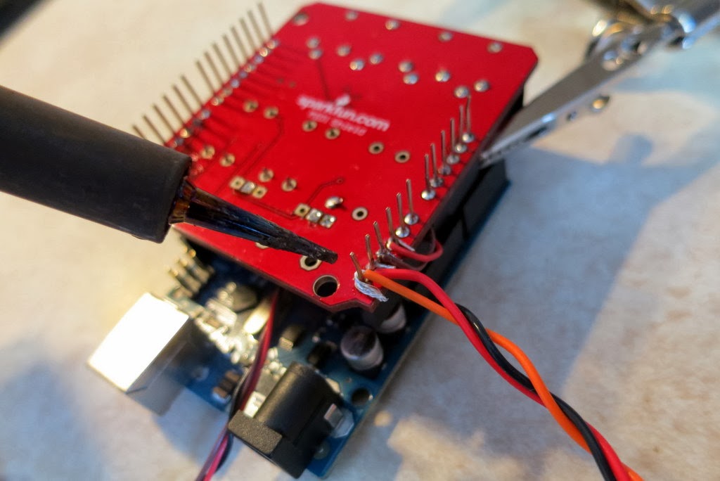 |
| A kludge. I'm soldering the wires to my audio jack to the pins on the MIDI Shield that will mate to the Arduino. Generally, this is not recommended, but it works. |
Once the wires are attached to the MIDI shield, then you just have to attach the jacks to the other end of the wires. As shown in the picture below, soldering to the jacks is much easier.
 |
| Soldering the wires onto the audio jack. These don't carry audio. They carry the CV Trigger signals. |
Finally, once all of the soldering is done, you simply mate the MIDI shield to the Arduino. The hardware is done!
 |
| My fully-assembled device for converting MIDI Clock to CV Triggers. |
Writing the Basic Software: For the Arduino, I wrote some software that listens for the messages coming in from the MIDI port. MIDI is quite general (it's not just about keeping time) so my Arduino is programmed to ignore most of the traffic on the MIDI bus. It is listening solely for MIDI Beat Clock messages (ie, code 0xF8). The MIDI standard says that there should be 24 of these messages arriving for every quarter note. So, if I want a 16th note arpeggiation, and since a 16th note is a 1/4 of a quarter note, I programmed the Arduino to issue a trigger pulse after every 6 MIDI clock messages (because 24 * 1/4 = 6). To actually issue a "trigger pulse", the Arduino briefly raises (or lowers) one of its digital output pins. That's the trigger signal. That's all it takes!
Adding Fancy Features: Once I had the basic software working, I started adding features. First, because some arpeggiators like upward-pulses and other like downward-pulses, I wrote the software to do both. That's why I use stereo jacks for my outputs...the "left" channel is upward going while the "right" is downward going. The next feature that I added is a second set of trigger outputs to drive a second arpeggiator (hence my inclusion of the second audio jack). Then, to be adjust the speed of the arpeggiators relative to the MIDI clock (do I want 16th notes? 8th notes? whole notes?), I program the Arduino to read the two potentiometers and to set the MIDI clock divider (that number "6" discussed in the paragraph above) to make the triggers come faster or slower. This is pretty sweet.
Sharing My Software: I case anyone is interested, you can get the latest version of my MIDI-to-Trigger Arduino software at my GitHub, which is here. If you make improvements, send me a pull request!
Trying it Out: So, for my initial trials, I kept the setup simple. My Korg Kaossilator is going to be my drum machine. I'm going to have it drive the arpeggiator on my Mono/Poly. So, as shown in the figure below, I connected the Kaossilator's "MIDI Out" to the "MIDI In" on the Arduino MIDI-to-Trigger Converter. Then, I connected a cable from one of my converter's outputs to the "Arpeggiator Trig In" jack on the back of my Mono/Poly.

You can see the connections to my MIDI-to-Trigger converter in the photo below.
 |
| Connections to my MIDI converter. The Kaossilator is coming in via the MIDI cable on the top left o the device. The Mono/Poly (off screen) arpeggiator trigger is driven by the 3.5mm audio cable on the bottom of this picture. |
As seen in the picture below, with all of these extra wires running around, the setup gets a little messy.
 |
| Zooming out to see the whole setup. Wires everywhere! |
Once it was all connected together, I started some drum loops on the Kaossilator. Then I activated the arpeggiator on the Mono/Poly, I set it to "Latch", and then I locked in a few notes. And then nothing happened. After chasing down a couple of bugs in my software, I tried again. And then again. And eventually, I got it to work. The arpeggiator was stepping in sync with the Kaossilator. It was glorious. As shown in the video at the top of this post, I can change tempo and it all keeps going in sync. It's pretty fun.
Next Steps: The next steps are to run the arpeggiator on my Mono/Poly and the one on my Polysix at the same time. That'll be a really fun. Look for a follow-on post!
Follow-Up: Two arpeggiators at the same time!
Awesome.
ReplyDeleteThanks, J! Do you synth? Do you hack? Do you do any synth hacking?
DeleteIndeed, I hack all my synths.
Delete:P
(Yash on Yahoo Polysix, Muffs, etc...)
Synth Hacker: Arpeggiator Fun -- My Midi-To-Trigger Converter >>>>> Download Now
Delete>>>>> Download Full
Synth Hacker: Arpeggiator Fun -- My Midi-To-Trigger Converter >>>>> Download LINK
>>>>> Download Now
Synth Hacker: Arpeggiator Fun -- My Midi-To-Trigger Converter >>>>> Download Full
>>>>> Download LINK i3
Hi Chip,
ReplyDeleteDid some cool hacks with my Arduino Uno and a small MIDI PCB circuit I literally hacked from an unused keyboard. Does your Polysix play a note when your ARP trig cable is in and you have already latched some notes on?
Here are three sound clips from my hacks on an Arduino Uno:
1. External CV control sweep for Cutoff:
https://soundcloud.com/yashn/cv-control-polysix-cutoff
2. External Arp trigger with random value to Cutoff CV Control:
https://soundcloud.com/yashn/korg-polysix-external-arp
3. MIDI & Arp Trigger sync:
https://soundcloud.com/yashn/korg-polysix-midi-to-arp
Cheers.
Re synth hacking: my first passion is actually composing with synths, especially for electronic-sounding music. However, the hobby and art can get very deep sometimes. I'm sure you know what I mean. I've spent a lot of time doing composition, but a lot of my time has also been spent to the detriment of composing music.
ReplyDeleteTime spent doing synthesis, hacking with DAWs, mixers and sound cards, is all time which could have been used to compose and record.
Going back to synths, all of them were hacked in some way or the other. Hacked my Roland D-10's drum sequence to compose whole songs on it. Hacked my Kurzweil K2500XS to incorporate additional third-party and custom samples and sounds as well as some of the sequences found in the K2600. Bought synths left for dead on eBay and Kijiji and brought them back to life, and the ones most subject to additional mods are the Poly-800, the DW-8000 and the Polysix, all Korgs for some reason.
But in fact, even the Alesis Micron and the Roland JX-8P which are not too hacked are candidates.
There are reasons to that, including affordability (the only synth I bought new was the Kurz a long time ago) although the end goal is to compose in a whole new environment made possible by my hacks with these same synths and perhaps some additional modules I am building.
But as mentioned, things can get deeper than planned. I wanted to finish a new album of songs and music last year. Guess what happened in the meantime...
Whoa, you can hack digital synths that are mostly-software? What can you do to those synths? I'm very intrigued!
DeleteChip
There's always a hack lurking somewhere! The Kurzweil allows you to burn data in its flash rom through the disk drive and files listing programs, setups and basically 'objects'. It also allows you to edit your own version of the compressed ROM samples and save them as sample and keymaps.
ReplyDeleteSince the last official Object file was less than the available Flash ROM, I built my own Object file by adding to it, adding my own Saw2 to make 'supersaws', adding my custom patches as well, some third-party patches, as well as some of the objects available in the K2600, the interactive setups, which are super powerful and great for composing.
Therefore, when I power it on, I have an enhanced, customised K2500, more powerful than a stock K2500. It will still be the same even after a hard reset since I put this all in Flash ROM.
For the D-10: I liked the synth, but I was miffed it didn't have a sequencer. It did have a drum sequencer. So I first thought of replacing some of the drum sounds in the synth by my own, e.g. a few keys for bass, a few keys for pads, a few keys for effects, other for counterpoints, etc... But, since it was a drum sequencer, the default setting was a very short release, hence all the other sounds were weird. I then changed the sounds to have their own envelopes, and then composed a lot of songs with the D-10 like that, pattern-based structure, with live playing while recording.
Great project.
ReplyDeleteI'm also in a quest. I'm trying to control two monotrons via CV, the idea is that given two midi notes arduino can decide wich note send to monotron #1 and the remaining note to monotron #2. I know arduino can do that, i've seen it, the problem is whether arduino can correctly assign a note to a monotron or not.
I'm new to this, and I'm a bit lost. Any suggestions may help.
Thanks in advance.
An Arduino can definitely do the thinking, but it isn't very good doing the CV generation.
DeleteFor the MIDI-to-Trigger hack shown in the blog post above, the Arduino just needs to generate an ON or OFF signal, which is a HIGH or LOW signal in Arduino-speak, which is a 5V or 0V signal in actual voltage values. The Arduino can do this easily.
The monotrons, however, will want you to apply voltages other than 5V and 0V. You can do this either by using either:
1) A digital Potentiometer: a digital pot is a chip that you buy where you can send it commands from the Arduino and its resistance changes...you'd use the digital pot in place of the touch strip on the monotron
or
2) A digital-to-analog converter (DAC): a DAC creates any analog voltage that you want (*way* better than the Arduino's built-in crappy AnalogOut() command). You'd inject this voltage into the Monotron in place of the touch strip. A DAC can be complicated, though, so you'll want to buy/use one with a great Arduino library.
The MCP4725 breakout from Adafruit is really good (http://www.adafruit.com/products/935) but it is only one channel, so it'll only control one Monotron To control 2 channels you'll need to use two MCP4725's (I'm not sure this'll work) or you'll need to get a two channel DAC chip. I've been playing with the MCP4922...
http://synthhacker.blogspot.com/2013/09/first-pcb-mcp4922-dac.html
A year or two ago, I successfully used a MCP4922 to control one Monotron. It's wasn't easy, but it was fun! Then, I did more mods to the Monotron, and I broke it. Sometimes, that's how it goes...
Good luck!
Chip
Thanks for sharing the code
ReplyDeletewill try it out!
hi chip, this is really cool! is it possible to also convert the signal and pass it through to a usb host shield for midi-usb devices?
ReplyDeleteHi there, great work. I don't have any problems to sync 2 synth or drum machines, the thing is when i try to sync more of 2 equipment. do you have or know any project whit 3 or 4 midi outs? Regards
ReplyDeletehttp://www.midisolutions.com/prodqth.htm
DeleteHi!
ReplyDeleteCongrats, its a nice code what you have in there, where can I find the code for this Arduino Project?
There is a link to the code in TFA
ReplyDeletehttps://github.com/chipaudette/ArduinoMidi
Thanks for the hack! I'm use the uno/midi setup to use a shared midi Tim clock to clock a sequencer that needs a cv input. That is I turn controlling the pitch of my moogsub fatty. I'll post a video when the parts come and is completed.
ReplyDeleteHi Chip,
ReplyDeleteFinally i get my Arduino+SparkFun and your Project works Awesome!
Do you think is possible to modify your code to just send CV clock to 3 or 4 outputs (A2 - A5)? Since I just want to synchronize my Gameboys I´m wonder if you can help me with the code? Thank you very much!
Synth Hacker: Arpeggiator Fun -- My Midi-To-Trigger Converter >>>>> Download Now
ReplyDelete>>>>> Download Full
Synth Hacker: Arpeggiator Fun -- My Midi-To-Trigger Converter >>>>> Download LINK
>>>>> Download Now
Synth Hacker: Arpeggiator Fun -- My Midi-To-Trigger Converter >>>>> Download Full
>>>>> Download LINK