Showing posts with label Teensy. Show all posts

Monday, September 13, 2021

DIY Vocoder: Robots Feelin' It

The vocoder.  It's undeniably attention-grabbing.  And, for many, it is also completely off-putting.  It is absolutely the anchovies-on-pizza of the synthesizer world.  I like anchovies.  But would I like a vocoder?  I needed to find out...so, I built my own!


What is a Vocoder?  A vocoder is an effect that makes a synthesizer sound like your voice.  You sing or talk into a microphone and you play your synthesizer.  The vocoder transfers certain qualities of your voice onto your synthesizer.  Like a wah pedal, equalizer, or filter, a vocoder doesn't make its own sound; it manipulates and changes the sound from another device, such as a synthesizer.

Setup.  As shown below, a vocoder needs a microphone and a synthesizer.  The two are plugged into the vocoder.  The output of the vocoder goes out to your PA or DAW.  Pretty easy.  It's what's inside the vocoder that is the magic.

Starting Simple: 1-Band Vocoder.  Before we get too deep, we should look at a simpler example.  Since a vocoder processes many frequency bands in parallel, lets start by looking a simple 1-band vocoder.  As I've illustrated below, a 1-band vocoder has two elements: a block to sense the instantaneous loudness of the voice ("RMS", which is an envelope follower) and a gain block (a VCA) to change the loudness of the synth in response to the voice's loudness.  This is the core unit from which we will build up a vocoder.
 

What Does It Sound Like?
  This basic effect changes the overall loudness of the synthesizer.  When the voice is loud, it allows the synth to be loud.  When the voice is quiet, it forces the synth to be quiet.  It responds very quickly and very naturally.  While that is cool, it does not actually sound like the voice. Just changing the loudness is not enough to sound like your voice. 

Tracking Your Voice's Formants.  To add more voice-like qualities, a real vocoder looks at the loudness of many different frequency regions of your voice.  The different frequency regions are chosen to sense the different frequency regions associated with the different vowel sounds.  As you make the different vowel sounds, you change the shape of your mouth (and nasal passages) to enhance or attenuate the different harmonics contained in your voice.  This shaping is why an "A" sounds different from an "E" and from an "O"; the peaks in the frequency response (the "formants") are very different for the different vowel sounds.  A vocoder detects this frequency shaping and applies the same frequency shaping to the synthesizer's audio.  The result is a voice-like quality to the sound of the synth.


Multiband Vocoder.  Our 1-band vocoder changed the loudness of the overall signal -- all frequencies were affected equally.  To make the synth more voice like, we want to sense the frequency shaping (the formants) as it dynamically changes to make the different vowels.  Therefore, we need to break up the audio so that we can control the loudness of individual slices of the frequency spectrum.  To make this give us this finer control, we copy our 1-band vocoder many times in order to get a multiband vocoder.  The illustration below expands our 1-band vocoder into a 3-band vocoder.

Breaking Up the Audio into Frequency Bands.   The core of this system are still the green RMS blocks (envelope followers) and orange gain blocks (VCAs) as discussed before.  This system still controls loudness.  But, note that we precede each of these channels with a bandpass filter.  Therefore, each channel is controlling the loudness of just one frequency region.  In this simple 3-band example, the first filter might isolate the low frequencies so that that loudness of the low frequencies are made to be the same between the synth and the voice. The middle filter and last filter would do the same for the middle and high frequencies.  Now, we are impressing more of the voice's qualities onto the synth.  A real vocoder uses 8-16 of these channels, which gives it much better resolution, making the output even more voice-like.

Making My Own Vocoder.  In the old days, the bandpass filters, RMS blocks, and gain blocks would all be implemented by actual electronic circuits.  Today, however, it's much easier to write signal processing software to perform these functions.  That's what I did.   I used an open-source digital audio device from Blackaddr (the "Teensy Guitar Audio Pro", TGA) and wrote software to implement the vocoder.  The TGA uses a Teensy 3.6 as its processor, which can be programmed in the Arduino IDE, This is great because Arduino is what I use for many of my other synth hacks.   I've shared my Teensy/Arduino vocoder software on my GitHub here.

Filtering and Processing Speed.  Having up to 16 channels, and needing at least two filters per channel, a vocoder needs a lot of filters.  So, your choice of filter is important as it can consume a lot of the available processing power.  I used the multimode filter model that comes in the Teensy Audio Library  They implemented the filter as a time-domain IIR filter with fixed-point operations.  I ended up using two filters in series to sharpen the filter's response (though I'm not sure that was really necessary).  Even with the burden of the extra filtering, the Teensy 3.6 was fast enough to enable a 16-band vocoder.  With the double-filtering, that's 64 filters in total!  I was pleased.  


Filter Frequencies.  An important choice is to pick the frequency bands for your vocoder's filters.  I know that the frequencies should be tailored to the human voice, but I had no specific guidance on what frequencies to use.  After a bit of trial-and-error, I chose to center my first filter at 125 Hz and then I step the frequency upward by a factor of  1.319x for each subsequent filter.  This seemingly-bizarre value is partway between half-octave steps (1.414x) and third-octave steps (1.260x).  Using this step size, my filters end up being centered at: 125 Hz, 165 Hz, 218 Hz,...<etc>..., 4595 Hz, 6063 Hz and 8000 Hz.  To me, this felt like a good span for the human voice.

Make Your Own!  To be clear, when I wrote this vocoder, many of my choices were arbitrary.  Don't be afraid to make your own choices!  Choose a different type of bandpass filter.  Choose different filter frequencies.  Use FFTs instead of time-domain filters.  That's the beauty of hacking using open technology: you can try things out for yourself!  Go and have fun!

Thursday, September 2, 2021

DIY Beat Box to MIDI Converter

It was the best spouse's workplace party ever.  I got to talk with a guy about how he could make his modular synth respond to his voice.  How cool is that!  I was inspired.  So, while I don't have a modular synth, I do have an 808-style drum machine.  Here is a joyous toast to you, the best spouse's workplace party ever: my voice-driven drum machine!


DIY Voice-to-MIDI Converter.  The key to this hack is making a device that can listen to my voice and can distinguish between my different voice sounds.  When I make a low-pitched sound ("boom"), it should issue a MIDI command for a kick drum.  When I make a high-pitched sizzly sound ("tsst") it should command a hi-hat.  And when I make a mid-frequency sound ("kuh"), it should command a snare/clap sound.  I have a mic for my voice.  I have a MIDI-compatible drum machine for drum sounds.  What I needed was a voice-to-MIDI converter.  That is what I made.


Hardware.  For this voice-to-MIDI converter, I used an open-source audio processing device called a "Teensy Guitar Audio Pro" (TGA) from Blackaddr.  As the name implies, it is intended for guitar.  But, knowing that dynamic microphones share many qualities with guitar pick-ups, I knew that the device would work just fine with my old, cheap dynamic mic.  The TGA has tons of hardware features, but what's important for this hack is that it has a MIDI output.  What hackable guitar processor includes MIDI?  This is what makes the TGA the perfect tool for this hack.

Teensy Guitar Adapter Processes the Mic Signal to Generate MID Commands

Programmable.  The processor in the TGA is an open-source device that is programmable through the Arduino IDE.  This is perfect for me since many of my hacks are built around Arduino.  I have an old version of the TGA, which is built around a Teensy 3.6, which is 180 MHz processor with floating point support.  Newer versions of the TGA bump that up to a Teensy 4.1, which is 600 MHz!  Either way, the Teensy is great because there's an Audio-processing library and an active community to learn from.  The fine folks at Blackaddr also provide a bunch of example programs to help with TGA-specific features.

The Teensy Guitar Adapter is Powered by a Teensy 3.6

How Are the Sounds Different?  The main challenge for me was designing the audio processing.  How do I get the Teensy to automatically detect which sound I was making with my voice?  The first step is always to figure out what you, as the human, to understand what makes the sounds different.  A good way to do this is to make recordings of the three sounds ("boom", "tsst", and "kuh") and to compare the frequency spectrum of each.  


Frequency Spectra.  Using the TGA as an audio interface for my computer (thanks to Teensy's USB Audio features!), I plugged in my microphone and recorded myself beat boxing.  I then manually sliced up the recording and excerpted the first 50 msec of each sound sample.  I pulled the excerpts into Matlab and computed the average spectrum for all the kick sound ("boom"), hi-hat sounds ("tsst") and clap sounds ("kuh") that I made.  You can see the average spectra below.

Lows, Mids, and Highs.  After normalizing all the excerpts to the same loudness (I don't want to throw off my voice classifier just because I happened to be quite or loud), the plot of the spectra shows what is the same and what is different about my three voice sounds.  In their normalized form, the amount of low frequency sound is similar.  But, the mids and highs are quite different:
  • The "boom" sound for the kick has little mids and little highs. 
  • The "tsst" for hi-hats have little mids but lots of highs.  
  • The "kuh" for the clap has lots of mids and lots of highs.
Classify Based on Mids and Highs.  So, the mids and highs are the key.  The figure below plots measurement for each individual beatbox sound that I recorded.  I plotted each excerpt's mid-frequency energy on the horizontal axis versus its high-frequency energy on the vertical axis.  Notice how the three types of sounds nicely separate from each other!  This plot is the key to making the voice classifier. 

All The Pieces of the Voice Classifier.  Having figured out how to distinguish between the three voice sounds, we know what we need to do.  Once we detect that a voice sound is preset at all (such as by simply looking for the overall loundess of my voice), here are three steps of the classifier:

  1. Measure the mid and high frequency energy (via some sort of filters)
  2. Compare the measured mids and highs to the 2D plot above classify the sound
  3. Issue a MIDI command for the sound we want

Implementing the Classifier via Filters.  Based on the average spectra, it looks like I want a lowpass filter with a cutoff around 1200 Hz, a bandpass filter passing 1200 Hz to 3000 Hz, and a highpass filter with a cutoff at 3000 Hz.   Given the filter types available in the Teensy Audio library, I used the state-variable filter because it offers lowpass, bandpass, and highpass outputs.  To get a sharper frequency response, each "filter" is actually three of these filters in series.

Threshold Detection.  With the signals filtered into three streams (low, mid, high), I wrote a simple audio class to compute the RMS envelope of each signal.  After extracting he envelop, I compare the level to a threshold to detect when the sound is loud enough that we can assume that my voice is present.  That is a "detection".  There is a voice sound that needs to be classified into kick, hihat, or clap.

Classify.  Having run my three filters, I have three measured values for each detection: the low-frequency loudness, the mid-frequency loudness, and the high-frequency loudness.  I normalize for the overall loudness by dividing each value by the sum of the three values.  Then, for the mid and high frequency values, I compare them to my 2D plot shown earlier.  Where do they fall in this plot?  Depending upon where it falls, I issue a MIDI "note on" for the kick (note 36), hi-hat (note 42), or clap (note 39).

Tuning  Of course, the development of this hack did not go as smoothly as was implied here.  It took a lot of experimentation and tuning.  The final code is here on my GitHub. 


Having Fun. Once I got it working, it was fun to make deep 808 kicks with my voice.  It was fun to use my same voice sounds to trigger other drum sounds (like the cowbell!).  And, since the system simply outputs MIDI notes, I used it to drive my synthesizer.  If I had a sampler, it would have been fun to trigger silly sounds on the sampler using silly sounds from my voice.  If you try this yourself, let me know what fun you have with it!

Sunday, November 8, 2015

Korg Polysix with Velocity Sensitivity

In truth, a Korg Polysix has rather limited features.  But, because it is an analog synth, it is open to modifications.  And so I've dived in head first.  I've already added aftertouch and portamento, controllable detuning, sustain pedal, and Moog-style legato triggering.  My most recent modifications began a few weeks ago, when I decided that I wanted my Polysix be velocity sensitive.  After a bunch of explorations and trials, I've finally pulled together all of the pieces.  That's today's story.  But first, here's a demo!  (Note, the bass distorts my laptop speakers, too.  Go for headphones.)


The Pieces:  The addition of velocity sensitivity to my Polysix builds upon many of the previous mods that I've done.  The core enabler of this mod was the fact that I had already replaced the stock Polysix keybed (which does not transmit velocity information) with a new Fatar keybed that is both velocity and aftertouch sensitive.  It's sweet.  As shown below, in my modified Polysix, the data from the new keybed is fed to an Arduino Mega, which assigns each new note to one of the six voices in the Polysix.  To modulate that voice in response to the note's velocity, I also feed the velocity information to my new "Velocity Processor", which then does the actual velocity-based modulation.

My highly-modified Polysix.  The newly-added "Velocity Processor" is highlighted in yellow.

Velocity-Based Modulation:  So what kind of velocity sensitivity did I implement?  I chose to modulate the intensity of the filter envelope.  As you heard in the demo, the intensity of the filter opening and closing gives a strong sense of articulation and dynamics.  In a stock Polysix, the intensity is the same for all voices (as set by the "EG Int" knob).  My goal was to dynamically change the envelope intensity based on how hard I hit the key.  As shown below, I chose to attenuate the filter envelope based on the note velocity.  At maximum velocity (MIDI 127), the envelope would be at its full intensity (as set by the "EG Int" knob, as before).  At lower velocity values, the intensity would be progressively smaller.  As a result, notes that I press hard should have a strong intensity and notes that I press lightly will soft intensity.


Scaling the VCF Envelope Based on the Note Velocity

Hardware Approach: After studying the Polysix schematic, and after figuring out how the VCF envelope multiplexing and how its associated addressing and synchronization works, I settled on the plan that I would manipulate the VCF envelopes in the multiplexed portion of its circuit.  Being multiplexed, I only have one signal line to manipulate, instead of six individual signals (one for each voice).  Sure, the signal on that one multiplexed line is changing very quickly (all six envelopes are time-sliced onto a single line), but I've already proved that a Teensy 3.1 plus a digital potentiometer can keep up just fine.  So, my hardware plan was settled -- I'd insert my Velcoity Processor right after the VCF Multiplexer (IC24) on the Polysix's KLM-366 PCB.


Building It:  In the Polysix, I was happy to see that IC24 is socketed, which means that you can pull out the chip and insert all sorts of fun new circuitry via the now-empty socket.  And so that's exactly what I did.  I took a piece of protoboard, soldered on the Teensy 3.1, the digipot, and IC24 itself.  More details on the build are here.  I then inserted the assembled protoboard into the empty IC24 socket.  As you can see below, it's not too pretty.  It's not complicated, it's just messy.  Someone with more experience would certainly do this more cleanly.

My "Velocity Processor" Installed in my Polysix.  Lots of wires.  Someone smarter than me could surely do it more cleanly.

Arduino and Teensy Software:  Hardware alone does not make this modification work.  I also needed to write some software.  For example, I needed to program the Teensy (my "Velocity Processor") to keep up with the multiplexing circuitry and to drive the digipot to properly attenuate the envelope signal.  I also needed to expand the programming on the Arduino Mega (my replacement for the Polysix's "Key Assigner CPU") to properly route the velocity data from the keybed to the Velocity Processor.  While this routing of the velocity data sounds straight-forward, the need to support the Arpeggitor modes made it more challenging (note that the velocity-sensitive arpeggiator leads to fun effects, like being able to make some notes feel accented...definitely a cool effect).  In the end, the software writing went pretty smoothly.  My latest code for both the Arduino and the Teensy are on my GitHub here.

First Trials and Tweaking:  Once I got it all wired up and programmed, I started to play it.  The velocity sensitivity really makes it more expressive.  Velocity sensitivity also quickly exposes bad keyboard technique!  I need practice!  But, even with my poor technique, I felt that the velocity response wasn't quite right.  So, I spent some time remapping the velocity values to create a custom response curve.  Furthermore, to get a good electric piano/clav sound, I felt that I needed a little grit and compression in the sound.  So, I added a drive circuit, which will be the subject of another post.

Playing It:  Once I got it adjusted to my liking, I've had a lot of fun adjusting all of my traditional Polysix patches to best include the velocity capability.  I started with the piano and clav sounds (as seen at the top of this post) because they our ears most expect velocity dynamics with these kinds of sound.  Interestingly, though, even organ sounds (which are traditionally not velocity sensitive) can benefit from velocity dynamics.  Hitting the keys a little harder, gives the organ more "pop!".  You can here it this little carnie organ vamp:


Moving Forward:  My next step is to continue to refine the interaction of the velocity with the other synth's features.  For example, I'd like a way to turn off the velocity sensitivity so that the EG Int will work as it does in a stock Polysix.  To do this, I simply need to wire up a switch, or re-purpose one of the switches already on the back of the synth.  Also, I need to further tweak (and then write-up!) my drive circuit.  It is critical for the velocity-sensitive piano/clav sounds, but I've found fun uses with other sounds, too.  Finally, I also want to improve how the velocity interacts with the Unison and Chord Mem modes of the synth.  It doesn't feel quite right yet.  So there's lot's to do!  But first, I've got some playing to do.  :)

Update: I tried adding diode-based distortion to add some grit to my EP/clav sounds...but I didn't like it very mcuh.

Update: I tried overdriving one of the Polysix's OTAs to add some grit and I liked it a lot!

Thursday, October 29, 2015

Building my Polysix Velocity Processor

Today it starts.  We've talked enough about my dreamy dreams of velocity sensitivity for my Korg Polysix.  It's time to get down to business.  It's time to apply what I've learned about its multiplexing and about its synchronization.  It's time to build something.  Let's smell the solder!

First Generation "Velocity Processor" Installed in my Polysix

Where to Insert My Circuity:  Before I solder anything, I need to figure out where I am going to insert my "Velocity Processor" into the Polysix circuit.  As discussed in my previous post, I want to put it after the multiplexer (IC24) but before any of the other envelope and VCF processing.  The figure below shows, notionally, how I'll use several of the signals associated with IC24.  What is the easiest way to get physically access to these signals?


Use the IC24's Socket!  When I opened up my Polysix and too a look at IC24 to see what connection points might be available, I was immediately struck by the fact that IC24 is socketed!  By pulling IC24 out of its socket, I now have instant, easy, and easily-reversible access to most of the signals that I need!

Here is the socket for IC24.  The perfect place for inserting my Velocity Processor.

Which Holes for Which Signals:  Looking at the Polysix schematic, I see that I can get almost all of my signals from this one socket: +5V power and ground, the three addressing lines (A,B,C), the inhibit line (INH) as well as a place to inject my velocity-modified, multiplexed envelope signal.

The signals that I will use for my Velocity Processor -- all available from the socket for IC24.

How to Connect to the Socket:  While the socket is a very convenient way to get signals without modifying the Polysix PCB, I still had to find the right hardware that would mate into the socket.  After trying a few options, I found that the legs on the Arduino-style "stackable" headers fit very nicely into the socket.  My plan, therefore, would be to mount the stackable headers to a protoboard, solder them in place, and have their legs reach down and mate to the socket.  Since these stackable headers have really long legs, they'll let the protoboard (with all of my other components) stand above the other components on the Polysix PCB.  It'll be great!

Arduino-style "stackable" headers fit into the Polysix IC sockets.

Why Not Use Regular 0.1" Pins?  Arduino fans may immediately wonder why I'm using these stackable headers when it appears that 0.1" male pins (also popular with Arduino projects) would be cheaper and less bulky.  In fact, I did try to use these pins.  But they don't fit in the socket.  After looking at the detailed geometry of these pins versus the legs on the stackable header (shown below), I found that the pins are indeed thicker than the legs on the stackable header (0.64 mm vs 0.40 mm).  That's the reason that the pins don't fit.  That's the reason I'm using these stackable headers.  [Note: If you really want to use pins, perhaps the 0.45 mm pins of the Samtech TS-108-T-A will work.]

The common 0.1" male pins are too thick to fit. But pins the stackable female headers are thin enough to work.

General Configuration:  After looking at the space inside the Polysix, and after looking at the size of the protoboard that I had on-hand, I decided to configure the basic elements of my Velocity Processor as shown below.  The stackable headers are shown on the bottom right.  The digipot is on the left.  The Teensy 3.1 microcontroller is on the top.  Now we just need to figure out the wiring.

Here is my high-level plan: a Teensy 3.1 plus a digipot plus a pair of stackable headers.

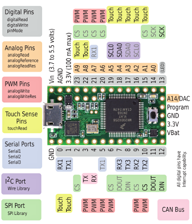
Connections to the Teensy:  Below is a picture of the Teensy with the pins labeled.  It shows which pins I'm going to use for the various connections.  Remember that the Teensy is only a 3.3V device whereas the Polysix's digital signals (the A,B,C addressing lines and the inhibit line) and the Serial connection from my Arduino key Assigner are all 5V signals.  Luckily the pins on the Teensy 3.1 are 5V tolerant, so I can attach those lines to the Teensy without damaging it.  Another side-effect of the Teensy being 3.3V is that its SPI connections to the digipot will also be 3.3V signals.  Therefore, the digipot will have to be provided with a 3.3V reference, which will come from the wire that I show attached to the Teensy's 3.3V supply.

Connections to my Teensy 3.1

Connections to the Digipot:  Below is a figure showing connections that I'm making to the pins of my digipot.  As mentioned above, the SPI logic signals are at 3.3V, so I connect the "VL" logic reference (pin 12) as well as to the other logic pins.  The multiplexed envelope signal (my "input" to the digipot), however, can span 0V to 5V.  Therefore I set VDD to +5V and VSS to ground.

Connections for the Digipot to handle the 0V-5V Multiplexed Envelope Signal

The Wiring Plan:  The figure below shows my wiring plan for the Teensy, digipot, and IC24 socket.  Of course, I still need IC24 itself to function within the circuit.  Therefore, I had the brilliant idea to insert another IC socket into the stackable headers!  Isn't that brilliant!?!  I happened to have a spare IC socket whose legs seemed just long enough to fit in the big holes of the stackable header.  So, I can build my velocity processor as shown below, insert the board into the vacated socket for IC24, and then stick IC24 into my board.  That's the plan, at least.

The First Wiring Diagram for my Velocity Processor.  Note IC24 sitting on top of the stackable headers in the bottom right.

The Wiring Reality:  Below, you can see the protoboard after I wired and soldered everything in place.  You can even see how I inserted IC24 in place.  On the underside of the board, you can see the pins sticking out that will fit into the Polysix's socket for IC24.

The first version of my Velocity Processor

Testing It:  At the top of this blog post is a picture of this first version of my Velocity Processor mounted within my Polysix.  While it did do something, I quickly discovered that my plan of sticking IC24 on top of the stackable headers wasn't working.  The pins of my add-on IC socket did not mate securely nor reliably to the stackable header.  Sad.

The New Wiring Plan:  The solution to this problem was to move IC24 off the stackable headers and down onto the protoboard.  I had resisted doing this because it mean adding 16 wires (one for each leg of IC24) between the stackable headers and the new spot for IC24.  It was going to be an annoying task, but I needed to do it.  <Sigh>

The Second Wiring Diagram for my Velocity Processor.  Note that IC24 has been moved and 16 additional wires have been added to connect it to the circuit.

The Completed Wiring:  Below is a picture of my Velocity Processor after moving IC24.  You can see it on the top right.  You can also see the rainbow of wires that I had to add to connect IC24 back to the stackable headers.  All those extra wires sure made it ugly.  But, the task is done.

By moving IC24 to its own spot on the top right, the extra wiring really made it ugly.

Plugging It In:  Below is a picture of my revised Velocity Processor mounted within my Polysix.  All of the signals that it needs come up through the IC24 socket into which it has been mounted.  The only exception is the serial communication signal that comes from my Arduino Key Assigner.  That simplicity is pretty nice.

My revised "Velocity Processor" installed in my Polysix. 

Next Steps:   I need to finish the software on the Velocity Processor and I need to write the companion software for the Arduino Key Assigner so that it conveys the velocity data from the keybed to the Teensy.  Then I can test it and make sweet, sweet music.  Stay tuned!

Update:  It lives!  Check out the demo here.

Saturday, October 17, 2015

Teensy with AD5260 Digipot

Yesterday, I showed how I soldered a surface-mount digipot, connected it to an Arduino Uno, and got an update rate of just over 60 kHz.  It was pretty fun to get the whole thing working so well.  For my envisioned use of this thing inside my Korg Polsix, however, I need a microcontroller with a little more speed than the Arduino.  It needs to be able to drive the digipot at high speed and do other tasks like listen to messages coming over the serial line.  This post is about using a Teensy to drive the digipot instead.  How fast can it go?

Showing my Teensy 3.1 in the foreground.  It is indeed small.  In the back right is my digipot on its Adafruit SMT-to-DIP adapter board.  An Arduino Uno is in the back left, but it is just being used as a power supply to provide 5V.

What is a Teensy?  Teensy is family of microcontroller boards, like the Arduino is a family of microcontroller boards.  Teensy is aimed at folks who like the Arduino approach but who need something more capable.  In my case, I'm using a Teensy 3.1, which has a 32-bit processor that can run up to 96 MHz.  This is a lot more capability than the 8-bit, 16 MHz processor in the Arduino Uno.  Raw speed, however, isn't my only concern.  The Teensy is appealing to me because you can program it through the Arduino IDE and not have to learn some new way of programming microcontrollers.  Re-using what I know, yet getting more capability.  Sounds like a win-win situation.

Wiring the Digipot for 3.3V Operation:  One somewhat-important difference between an Arduino Uno and a Teensy is that the Teensy operates at 3.3V instead of the Uno's 5V.  This means that the whatever is connected to the Teensy (like my digipot) must be able to respond to the lower voltages.  Lucikly, my digipot is compatible with either 3.3V or 5V logic, so everything should work fine.  The biggest difference is that the output of the digipot (because of the now-smaller 3.3V input signal) will be limited to 0-3.3V, instead of the 0-5V signals seen with the Uno.  For this test, the smaller voltage output is not a problem.  This test is about speed.

Signals to use for testing the digipot with a Teensy 3.1, which uses 3.3V logic.

Wiring to the Teensy:  From the picture above, I'll drive the digipot by providing it power at 3.3V and by sending it commands over via the Teensy's SPI pins.  Looking at the pin map for the Teensy 3.1, I easily see the location of 3.3V and gnd.  Looking for the SPI pins, I see "CS", "SDOUT" and "SCK" on pins 10, 11, and 13, just like on the Arduino Uno!  Maybe that's by design, or maybe it was by coincidence.  Either way, it's comforting to see things being so similar.  So, overall all, as seen below, the wiring is basically the same as it was for the Uno.  Great.

Wiring a Teensy 3.1 to the my digipot via a solderless breadboard.
I connected power (3.3V), ground, and the three lines for the SPI bus.

Teensy Add-On for the Arduino IDE:  With the hardware elements all arranged, it's time to program the Teensy.  Since I want to do this via the Arduino IDE, I needed to first download the "Teensyduino" add-on from the maker of Teensy.  It's pretty painless.  During installation, the installer provides you the option to pre-install a bunch of libraries that Teensy supports.  I chose to install them all, but for this test, you probably just need to install the SPI library.  Either way, it's easy.  Once the Teensyduino software completed its installation, I started the Arduino IDE like normal.  Once it was open, I went under the "Tools" menu (as shown below) and told the Arduino IDE to target the Teensy 3.1 instead of the Arduino Uno.  Done.

I'm switching the Arduino IDE to target my Teensy 3.1 instead of my Arduino Uno.

Programming the Teensy:  With the Teensyduino add-on, my hope was that I could rely on all my Arduino knowledge and not have to learn a new command set just for the Teensy.  Relying on this hope, I simply opened up my existing digipot test program (written for the Arduino Uno) and told the IDE to recompile (Verify" in the language of Arduino).  It was successful!  It recompiled without any changes needed for the Teensy.  Fantastic!  Now, to actually transfer the program down to the Teensy hardware, one has to hit the pushbutton that's on the Teensy board.  When I did that, the program zipped down to the Teensy and I was good to go.  Very smooth.  Very nice.

Driving the Digipot with my Teensy:  With the Teensy programmed and ready-to-go, I hooked up all the wires between my breadboarded digipot and the Teensy according to the figure that I showed earlier.  I then plugged the Teensy into its USB cable (to provide power) and connected my oscilloscope to the output of the digipot.  I saw step-wise changing output voltages, just like I expected.  It worked!

My test setup.  Teensy on the bottom left.  Digipot on a solderless breadboard on the bttom right.  My oscilloscope shows a very quickly changing output signal from the digipot.  It works!

Is it Faster?  How fast could the Teensy change the pot's value?  Very fast.  Very very fast.  As shown in the screenshoot below, it was able to change the value six times in 8.1 microseconds (usec).  That's a mere 1.35 usec per change.  That's an update rate of 741 kHz!  By comparison the Uno required 16 usec, which was an update rate of 62.5 kHz.  So, the Teensy was about 12 times faster for this task.  That's fantastic.  Interestingly, the ratio of the their clock speeds (Teensy = 96 MHz, Uno = 16 MHz) is only 6x, so by actually showing a 12x increase in speed, it appears that the Teensy is much more efficient per clock cycle at this task than the Arduino.  Very cool.

[Note: Based on questions I've received...yes, I did disable the println() and delay() commands when testing at full speed.  I love that you folks are reading in this kind of detail! :) ]

Screenshot of the output of the digipot when being driven at full speed by the Teensy.  Note that it completes a six step cycle in 8.1 usec, which means that each step is only 1.35 usec, which means that the Teensy can drive the digipot with an update rate of 741 kHz.  Fast!

Extra Capacity for Other Tasks:  If I use this Teensy+Digipot setup in my nefarious plans for my Korg Polysix, I do not need it to update this fast.  At worst, I'll need it to update every 20 usec, which means that the Teensy can do its update at its native 1.35 usec speed and then wait around for the other 18.65 usec and do other tasks.  In other words, it'll only be busy (1.35/20) = 7% of the time.  The other 93% of the time, it'll be free to do things like servicing in-coming Serial messages.  I like having that much margin.  It gives me confidence that the Teensy can perform all of its tasks dependably.  My conclusion is that I've found my winning hardware combination for my Polysix modifications.