Showing posts with label Portastudio. Show all posts

Saturday, March 8, 2014

Portastudio - Voltage Control of Speed

After my experiments with live looping using my Portastudio 424, I keep thinking about what interesting modifications I can do to push the Portastudio into unexpected places as a performance instrument.  One idea was to expand the user control over the playback speed of the tape so that I could arbitrarily vary the pitch of the recorded audio.  Sure, the 424 gives some control over the tape speed, but it does not allow you to smoothly span a wide range.  So, I started looking into how I could modify the 424 to give me what I wanted.  Ideally, if I truly get aribrary control over the tape speed, I could turn my Portastudio into a monophonic Mellotron, which could be kinda cool!  Here's the story of what I've discovered....

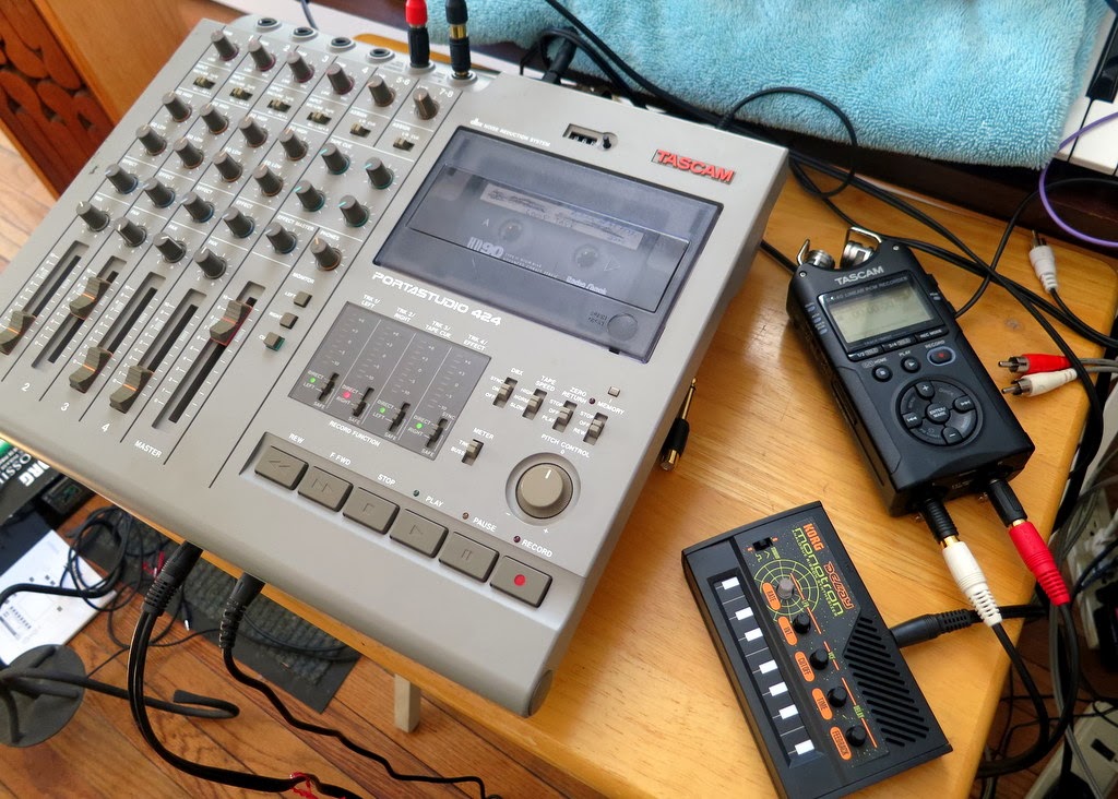
Built-In Tape Speed / Pitch Controls on my Portastudio 424
Built-In Pitch Controls:  As shown in the picture above, the Portastudio 424 comes with two user controls over tape speed.  First, there is a 3 position switch that sets the gross tape speed to either "slow" (15/16 inch per second), "normal" (standard 1 7/8 inch/sec), and "high" (3 3/4 inch/sec).  Assuming that it is usually set in the "normal" position, this switch lets you either drop the pitch by an octave or raise the pitch by an octave.  If you want finer control, you can use the pitch adjust knob.  Unfortunately, this only allows you to lower or raise the pitch by about 2 semitones.  So, there is a big gap between the gross tape speed switch and the fine pitch adjust knob.  I would like to modify the Portastudio to allow smooth changes between any pitch.  Let the hacking begin!

Opening the Portastudio, you can see the cassette and motor
assembly in the upper right.
The Cassette and Motor Assembly:  My first step was to open up the Portastudio to see how the cassette playback assembly is put together.  As you can see above, opening the Portastudio reveals a big circuit board that surrounds an assembly that holds the cassette, motors, and other mechanical bits.  Looking in detail at the cassette and motor assembly (picture below), you can clearly see the thin metal capstan and its corresponding pinch roller.  The capstan (and its roller) are what pull the tape over the playback head.  It is the capstan that controls the speed of the playback.  Controlling the speed of the capstan is the key to controlling the speed of the tape playback.

Zooming in on the cassette and motor assembly, you can see the capstan
and its mating pinch roller.  This is what controls the tape speed.
Capstan Motor:  Removing the cassette and motor assembly from the Portastudio, the picture below shows its underside.  It is a very complicated mechanical assembly with multiple motors, gears, belts, and circuit boards.  Staying focused on just the elements associated with the capstan, one can see a big flywheel that is directly attached to the backside of the capstan itself.  The flywheel is driven from a belt attached to a the capstan motor.  The capstan motor is attached to a circuit board via four electrical terminals.  This must be how the speed of the capstan is controlled.

Looking at the underside of the cassette and motor assembly.  You can
see the capstan flywheel, which is belt-driven by the capstan motor,
which I'm probing using my clip leads.
Four-Wire Connection:  Frankly, I was surprised to see that the motor had four wires to control it.  Not knowing anything about cassette players and capstan motors, I expected to find a basic DC motor with just two terminals.  I expected that the speed would be controlled by changing the DC voltage of the positive terminate or by using PWM of the the positive voltage applied to the motor.  Apparently, that's not the case.  How is this motor controlled?

Rotating the cassette and motor assembly again.  Here you can see
that the capstan motor terminals are labeled 1-4.
Looking at the Schematic: When it isn't clear how something works, it is usually best to consult the schematic.  Sadly, I don't have a schematic for the Portastudio 424.  Even scouring the internet (and visiting some unsavory web forums) did not yield the schematic.  The closest that I got was on eBay where someone was selling a paper copy of the Service Manual (which includes the schematics) for the Portastudio 464.  Since the 464 and the 424 were out a similar times, my hope was that the schematics would be close enough to enable my hacks.  So, I ordered it.  When I arrived, I found that the capstan motor and speed controls (in the 464) were wired as shown below.  It clearly shows the four wire connection -- two connections for power (12V and ground) and two connections ("B" and "A") that loop out through the user controls.  These must control the speed.  But why are the connections configured as a loop, instead of just injecting a commanding voltage signal from the outside?

Schematic from the Portastudio 464 Service Manual.  Hopefully, it is similar to my Portastudio 424.
Probing my capstan motor, it appears that the motor terminals are reversed...on my Portastudio 424,
Pin 4 is ground, Pin 3 is +12V, and Pin 2 and 1 must be the ones shown above as "B" and "A".
Capstan Speed Control:  A little research on the internet yielded some information.  The key idea is that the capstan must spin at a very precise speed (or else you get "wow and flutter"), so capstan motors are built with some sort of closed-loop control system.  This means that they have a method of sensing speed and then adjusting their speed based on the sensed value.  In many cassette systems, this closed loop feedback is entirely within the motor body.  In more flexible systems (such as the Portastudios), two sense and command signals are brought out to allow for user adjustment of the pitch.  In this case, the sense and command signals must be terminals "A" and "B".  I do not know which is which.  So, I'll probe the signals to see what I get.

Assuming Motor Pin 4 is Ground, Here are the Voltages that  I Measured
 at Different Tape Speeds.  Pin 1 Appears to Control the Tape Speed.

Finding the Command Terminal:  Using my digital multi-meter (DMM) with the Portastudio turned on, I quickly determined that on my 424, Pin #4 is ground.  This is in contrast to the 464 schematic, which showed ground as Pin #1.  Regardless, moving forward, I put in a cassette and pressed play.  Then, using Pin #4 as a reference, I measured the voltage at the other three terminals for different speed settings.  The values are shown in the graph above.  As can be seen, the voltage at Pin #1 drops as the speed increases.  The voltage at the other pins stays the same (basically).  So, I think that this confirms that Pin #1 is the terminal for the speed command signal, because it is the only one that changes with speed.  It appears likely that Pin #3 is the power supply for the motor, because it is the highest voltage signal and stays firm at +12V.  Therefore, through process of elimination, Pin #2 must be the terminal associated with the speed sensing.

After recording a ~65 Hz tone at the normal tape speed, I see that there is a nice
inverse relationship between the motor control voltage and the resulting pitch.
Command Voltage:  According to the 464 schematic, the speed command voltage is set by drawing current out of the speed sense pin (Pin #2 in the 424), and altering the voltage delivered to the command pin (Pin #1 in the 424).  Therefore, we would expect the voltage at Pin #1 to be lower (ie, negative) relative to Pin #2.  The blue line in the graph above shows voltage measurements that I made that confirm this expectation.  As you can see, the slowest speed exhibits a voltage at Pin 1 that is about -0.5V relative to Pin #2.  As the speed is increased. the voltage at Pin 1 eventually reaches about -3.5V relative to Pin 2.  Again, this is the relative voltage...the absolute voltage (well, relative to ground) was shown in an earlier graph and is running between +8.5V and +11.5V.

Pitch vs Speed:  So now that we have a good handle on how the Portastudio changes the command voltage based on the user settings for the tape speed, there is still the question of how much the speed of the tape actually changes.  Since tape speed directly affects the pitch of the audio that has been recorded to the tape, I've decided to quantify the change in tape speed by recording a tone onto the tape (at "Normal" speed) and then measuring the frequency of the tone as I change the speed.  The results of this experiment are shown as the red line in the graph above.  As expected, higher tape speed results in higher frequency.  Plotting frequency directly against the capstan command voltage, we get the relationship shown below.  Nice and linear.  Excellent.

The relationship between control voltage and pitch is nice and linear.

Creating the Command Voltage:  OK, now we're getting serious.  If I really want to make a mellotron out of my Portastudio, I have to generate the precise command voltage in order to achieve the pitch that I want.  The "command voltage" is is the voltage at Pin #1 relative to Pin #2, both of which are riding well above ground.  Assuming that I'm creating my command voltage from a 0-5V sounce (such as from an Arduino or something), I need a circuit that will both boost the voltage up to the correct DC level and to adjust the voltage based on whatever is happening on Pin #2.  The circuit shown below should do exactly that.

Notional Op-Amp Circuit Configuration to Generate the Correct
Capstan Command Voltage (Pin #1) Given a 0-5V Input Voltage.
[Revised, Mar 9, 2014]

Picking the Right Input Voltage:  While the circuit above should achieve my goals, it is an inverting amplifier with respect to the input voltage that I'll be injecting.  This means that an upward-going input signal results in a downward-going output signal.  As a result, the relationship shown earlier in the frequency-vs-voltage plot shown earlier is inverted.  To account for the inversion, I made the graph below.  Also, because I actually care about the perceived pitch of the tone (the note on the scale), not the actual frequency of the tone, I converted "frequency" axis into "pitch".  With this new graph, I can choose how many semitones of pitch shifting I want (say, shift up an octave, which is 12 semitones) and then I can simply read off the voltage that I need to send to my op-amp circuit (in this case, +12 semitones requires a voltage of +3.25V.  Easy!

If I want to achieve a certain pitch, here is the relationship that
determines the control voltage that I need to generate.

Next Steps:  With all of this analysis, I think that I have figured out how to control the tape speed of the Portastudio 424 to get the pitch shifting that I want.  Now I have to go and try it out.  It's time to smell the solder!

UPDATE, Mar 9, 2014:  I tried building the original op-amp circuit that I showed.  It did not have the correct input-output relationship at all.  The problem was that I did not include any of the resistors (R3 and R4) that are now shown on the non-inverting input.  Ooops!  Adding R3 and R4, the input-output relationship is now correct.

Tuesday, February 18, 2014

Portastudio - Live Looping

I'm continuing with my goal of turning my Tascam Portastudio 424 into a live performance instrument.  A key step was to take a regular cassette tape and to turn it into a continuously looping tape.  At normal speed on the Portastudio, my loop tape gives about a 5 second loop.  In trying to use the Portastudio as a live instrument, I've been learning how to record to the loop tape and to play back from the loop tape all in real time.  As with any instrument, it takes time and practice to figure out the interesting techniques and effects that the instrument enables.  Below is a demo of what I've figured out so far.


Recording to Tape:  To record audio to tape, the Portastudio allows several different methods.  Which method you choose is driven by your needs.  Because I want to use it as a live looper, I'm hoping to find a method that causes the Portastudio to play back the recorded audio as a loop as soon as I finish recording recording it.  Ideally, this will happen with no break in the action.  While this is trivially easy on a digital looper like the Kaossilator, it is a little trickier on a tape-based machine, since live looping is not what this kind of tape-based machine is designed to do.

Punch-In/Punch-Out:  Luckily, the Portastudio is designed to allow you to easily toggle between record and play modes without stopping the tape.  This is the "punch-in"  / "punch-out" practice that allows one to, say, redo a guitar solo without affecting the guitar that was recorded just before and just after the solo.  When we use our loop tape instead of a normal tape, this means that we can hear our loops, then "punch-in" to overwrite all or part of the loop, and then "punch-out" to let the loop resume playing.  You start the process by simply hitting "play" on the Portastudio.  To "punch-in", you hit the Record button (or press the "punch-in/punch-out" footswitch, like I do in the video).  To "punch-out", you hit the Play button again (or press the footswitch again).  At no point do you hit Stop...it just keeps going continuously.

Input Setup:  The Portastudio can configure its inputs a number of ways.  To get the Portastudio to playback your newly-recorded audio as soon as you punch-out, you need to use the configuration shown in the pics below.  The key is that you setup your target track (in this case, Track 1) to record NOT what is directly plugged into Track 1, but instead to record whatever is on the master bus.  You do this by setting the Track 1 Input to "Mic/Line > L".  Here, it'll record whatever is on the left channel of the master bus.  Critically, when the Portastudio is not in record mode, this setting also causes the Portastudio to simply playback whatever is on that track.  This is how you get it to play back the audio (without any further action) as soon as you punch-out.

Overall Configuration To Record to Track 1 and then
Get Instant Playback of Loops After Punching-Out.

Detail view of input settings to record to Track 1 from the master bus and to get instant
playback after punching-out.  My input audio is from the black and red plugs on the
right, which are configured to inject it to the L-R on the master bus.

Cue Bus:  Once you get one track recorded, you'll want to listen to that track while you record the next tracks.  In normal operation, you'd just have those tracks play back their audio on the master bus.  But, once you configure Track 2 to record like we did for Track 1, it'll record everything on the master bus...including your already recorded audio on Track 1.  Bad.  So, what you do is silence the playback of Track 1 on the main bus (by pulling down the volume slider) and instead play Track 1 on the Cue Bus.  As long as your headphone (ie, the "Monitor" buttons) are set to Left+Right+Cue, you'll hear all of the audio nicely.  So, after recording each track to tape, silence it on the main bus and bring it up on the Cue Bus.  Now you're ready for the next Track!

Settings for the Cue Bus so that I hear all tracks via the Cue Bus,
except for Track 1, which was already set for the Master Bus.
Live Effects Loop:  Now we get tricky.  As you saw in the video, after I recorded four tracks onto my loop tape, I hooked up the Monotron Delay to be an effects box for the already-recorded audio.  I was able to selectively and dynamically send audio from different tracks to the Monotron for filtering and echo effects.  I did this by re-using the Cue Bus.  Once my tracks were all recorded, I did the opposite of what I described above -- I moved all of the tracks off the Cue Bus and put them all back onto the Master Bus.  I then set my headphones (ie, the "Monitor" buttons) to listen only to the Master Bus.  That way, I could selectively send channels to the Cue Bus (via the Tape Cue knobs shown above) without hearing it.  Interestingly, the mixed audio on the Cue Bus is available via the "Effects" jack on the back of the Portastudio.  Secretely, this output jack is a stereo output.  One channel is the Effects Bus (which, despite its name, is not helpful in this scenario) while the other channel is the Cue Bus.  So, I plug Cue Bus into the Aux In of my Monotron Delay.  I then leave the Monotron's output plugged into the Master Bus so that I can hear the echos.  Instant live effects!

Configuration of Portastudio to allow live effects using the Cue Bus.
Note that I did not use the Portastudio's Effects Bus, because it does
not allow 100% effected signal, some dry signal must always
be present.  Using the Cue Bus avoids this limitation.

So this is the best setup that I have found for doing live looping with the Portastudio.  The key with this method is that the tape never stops, so your groove can just keep on going.

Sunday, February 16, 2014

Portastudio - Defeating the Erase Head

As discussed in my last post, I've been exploring the use of tape loops in my Tascam Portastudio 424.  I'm trying to turn the old Portastudio into a live performance instrument, especially one the allows me to exploit the imperfections in audio cassette technology.  As I started to do live looping, however, I discovered that any loop that I recorded would have a gap in the audio.  I found that, to eliminate this gap, I needed to defeat the erase head on the Portastudio.  Today's post describes that story.  To get started, below are some audio demos with the erase head enabled (like normal) and with it defeated (which gets rid of the gap!).  There's a third track in the playlist that demonstrates how, with the erase head defeated, you can now layer multiple sounds on a single track of tape.  Fun!


The Portastudio 4-Track Cassette Recorder:  Below is a photo of the outside and of the inside of my Portastudio cassette recorder.  Since I have no schematic for my Portastudio (does anyone have one that they can send to me?), I'm forced to figure things out by physical examination.  So, like a doctor poking and prodding, let's begin...

My Tascam Portastudio 424, Outside and Inside

Erase Head vs Record Head:  Since I assumed that my problem with the gap in my recorded loops was due to the erase head, I began my examination with finding the erase head.  As you can see in the picture below, it is nicely labeled.  You can also see that it is indeed physically separated from the play/record head (by about an inch).  When recording (or playing), the tape passes over the erase head to be cleared prior to passing over the record head to receive the new audio.  As a result, there is always a one-inch section of the tape that will contain no audio at all.  This is the gap that I have been hearing in my loops.

The Erase and Play/Record Heads on the Portastudio
Follow the Wiring:  To figure out how I can defeat the erasing process, I looked at the wires that are connected to the erase head to see where they go.  As you can see in the picture above, the wires from the erase head are mostly black, whereas the wires from the play/rec head are gray.  Following those wires back to the main circuit board, I found that the gray wires (the play/rec wires) go back to the four individual circuits on the main PCB.  The erase wires, by contrast, all come back to a single 8-wire connector on the main PCB.

Seeing Where the Erase and Play/Rec Heads are Wired Back to the Main Circuit Board.

Unplug the Connector:  The easiest way to defeat the erase head is, perhaps, simply to unplug it.  So, that's what I tried.

To Disable the Erase Head, Just Unplug the Big Connector

What are the "Erase" Signals:  Because I was interested, I hooked up my oscilloscope to the pins on the connector that I just unplugged.  I wanted to see what signals where being sent to the erase head.  The pictures below show what I found.  The connector has 8 pins, and each pair seem to give similar signals (I'd assume that each pair represents a single channel on the 4-track tape).  For each pair of pins, one pin showed an 87 kHz signal with an amplitude of ~134 mV RMS.  The other pin showed no signal, so it might be ground.  I'm assuming that the 87 kHz is the bias signal used by cassette systems as the carrier for real audio signal that is amplitude modulated on that carrier.  Since this is the erase head, there should be no audio, so it should just be the 87 kHz signal.  This appears to be what I see.

Looking at the Signals on the Connector to the Erase Head.
Looks like the 87 kHz AC bias signal (Left) and Ground (Right).

Trying it Out:  So, with the erase head disconnected from the main PCB, I tried recording some audio.  As a sound source, I used my Korg Monotron with its funny little ribbon controller.  As you heard in the demo tracks tat the top, when I defeat the erase head (by disconnecting it from the main PCB), I successfully eliminate the gap from my looped audio.  Fantastic.

Using the Monotron Delay to Create Tracks on the Portastudio

Visualizing the Results:  In addition to listening to the demos, you can see the tracks visually in the spectrograms below.  All of the tracks show recordings from the loop tape of the Monotron.  The top figure shows a single loop of audio excerpted from a recording when the erase head was connected and active.  Note the half-second gap at the end of the loop, which corresponds to that one-inch piece of tape between the erase head and the record head.  The middle plot shows the result after I unplug the erase head.  Note that the gaps is gone...the loop is continuous.  This is what I hoping for.

Spectrograms of the Same Three Audio Demos From the Soundcloud Player at the Top of this Post.

Layering Audio in One Track:  Another important effect of defeating the erase head is that nothing clears the track between recordings.  So, when you go to record audio onto a track, it becomes layered on top of the audio that was already there.  An example of this sound-on-sound recording is given in the third audio demo (and in the third spectrogram above).  Here, I first recorded the basic warbling tone from the Monotron as already seen in my other examples.  This is "Layer A".  Then, onto the same track, I recorded the Monotron with wilder variations in pitch.  This is "Layer B".  As is clear in the audio demo and in the spectrogram, both layers are clearly there.  Note that this is not a mixture that has been done electronically (ie, read the previous track, mix it with the in-coming new audio, then record the mixed audio onto a fresh track).  No, this mixture is being done on the tape itself.  As far as I know this is very uncommon.

Imperfect Layering:  I believe that one reason why it is uncommon to mix audio onto tape this way is because the layering is far from perfect sounding.  Note that as "Layer B" dives from high-pitch to low-pitch (see the blue arrow), it seems to suppress a lot of the "Layer A" sound.  It's not until the pitch of "Layer B" raises a bit that the tone from "Layer A" sounds strong again.  To most people, this interaction between the two layers of audio would be an undesirable trait.  But, not for me...I'm purposely looking for unusual side-effects of using tape.  So, to me, this kind of weird artifact is gold!

Moving Forward:  Right now, to enable or disable the erase head, I need to use that connector inside of the Portastudio.  It would be great if I could put it on a switch so that it was accessible on the outside of the Portastudio.  Unfortunately, switching 8 signals (there are 8 pins on that connector) is a hassle.  I'm hoping that, with more exploration, I can confirm that I only need to switch 4 of the signals (maybe just the grounds need to be connected or disconnected).  If so, this will be a great behavior to have switchable.

Have any of you hacked your cassette recorders?  What have you done?