In my previous post, I described how I made an Arduino-based MIDI-to-Trigger converter so that I could combine my love of old-school arpeggiators with newer MIDI-equipped drum machines. I gave a video demo of me driving the arpeggiator of my Korg Mono/Poly using the MIDI Clock output from my Korg Kaossilator. In this post, I take it one step further. Today, I'm going for gold...I'm going to drive two arpeggiators at the same time. Twice the fun!
As shown above, the setup is pretty straight-forward. The Kaossilator is providing a MIDI clock signal. I connect it's MIDI Out to the MIDI in on my homemade trigger converter. My converter has two trigger outputs. I connect one trigger output to the "Arp Trig In" jack on the Mono/Poly and the other trigger output to the similar jack on the Polysix.
I'm Using Trigger Outputs for Dual Arpeggiator Glory!
Below is a demo using this setup. It is a single-take where all instruments are playing live without any sequencing or anything from the computer. It's just the arpeggiators from the two synths and the Kaossilator.
A key feature of the track above is that I set the arpeggiators to play at different rates. I did this using the potentiometer knobs on my MIDI-to-Trigger converter. The effect is apparent right at the beginning of the track where the Polysix is playing one note every four beats whereas the Mono/Poly is rippling out eighth notes. The Kaossilator is providing the drums. Without my MIDI-to-Trigger converter, it would not have been possible to keep the drums in sync with the two arpeggiating synthesizers. It's much more fun this way.
For a second demo of this setup, the track below is also a live-recording of the Polysix plus Mono/Poly plus Kaossilator. In this track, though, the kick drum and snare sounds are actually being produced by the Mono/Poly (it's a very flexible synth). The arpeggiating synth is the Polysix. Everything else (hi-hats, bass sounds, leads) are all from the Kaossilator.
So, that's the fun that I've been having hooking everything together. Sure, by modern standards of EDM, this might not be too exciting...but I could play with these kinds of sounds for hours. I just love the sound of it all.
Use the comment section below and share with me your own joys with arpeggiators!
I'm going to admit it...I love arpeggiators. I love their inhumanly-perfect, never-ending rippling waves of beautifully-synthetic tones. It's so hypnotizing to me. What I like even better is if I add a drum machine to play along with the arpeggiator. But how do you keep the two devices in sync with each other? In a previous post, I showed how I used the "trigger out" of my old TR-707 drum machine to drive the arpeggiator on my Korg Polysix. While that worked fine, my newer drum machines don't have trigger outputs. Instead, they output MIDI. Since my synths don't talk MIDI, today's post shows how I built a MIDI-to-Trigger converter using an Arduino. The video below is a quick demo...
What Does the Converter Do? I have two old synths -- a Korg Mono/Poly and a Korg Polysix. Both of these synths have a built-in arpeggiator and both synths have a jack on the back for "Arpeggio Trig In". If you send a voltage pulse into this jack, it will cause the arpeggiator to step to the next note. As a result, you can keep the arpeggiator in sync with old drum machines that have trigger outputs (such as my old TR-707). My Korg Kaossilator, however, is much newer and it does not output trigger signals. Instead, it sends out a MIDI clock signal. My synths are too old for MIDI. So, if I want to keep my Kaossilator in sync with my Mono/Poly or my Polysix, I need a device to listen to the MIDI messages and to issue trigger pulses at the right times. That's what my MIDI-to-Trigger converter does.
The Shopping List: The heart of my MIDI-to-Trigger converter is an Arduino Uno ($30). To enable it to receive MIDI messages, I used a Sparkfun MIDI Shield ($20) that has the female MIDI connectors and the associated electronics to get the MIDI messages into the Arduino. Helpfully, the MIDI shield also includes two potentiometers and three push buttons. Very nice! To physically connect the MIDI shield to the Arduino, I also had to buy some stackable headers ($1.50). Finally, to get the trigger signals out of the Arduino and headed towards my synth, I chose to buy some 1/8" stereo audio jacks ($1 each), though any jacks will do (1/8" or 1/4" or whatever). I chose to include two audio jacks so that I can drive two arpeggiators at the same time (ie, both my Mono/Poly and my Polysix) because, if one arpeggiator is good, two must be even better!
The components in my MIDI Clock to CV Trigger Converter.
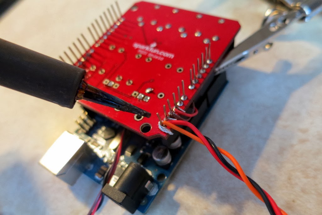
Assembling the Hardware: The MIDI shield comes as a kit that you need to solder together yourself, which is pretty direct and easy. After the shield was assembled, I then needed to attach my two audio jacks to convey the trigger signals out to my synths. Unfortunately, there are no solder holes on the Arduino or on the MIDI shield for attaching jacks or wires. So, I chose to solder some wires to the pins that connect the MIDI shield to the Arduino. Usually, this is not recommended approach, and you should be aware that it is a bit challenging to do (notice the tight space in the picture below) but it did work for me.
A kludge. I'm soldering the wires to my audio jack to the pins on
the MIDI Shield that will mate to the Arduino. Generally,
this is not recommended, but it works.
Once the wires are attached to the MIDI shield, then you just have to attach the jacks to the other end of the wires. As shown in the picture below, soldering to the jacks is much easier.
Soldering the wires onto the audio jack. These don't carry audio.
They carry the CV Trigger signals.
Finally, once all of the soldering is done, you simply mate the MIDI shield to the Arduino. The hardware is done!
My fully-assembled device for converting MIDI Clock to CV Triggers.
Writing the Basic Software: For the Arduino, I wrote some software that listens for the messages coming in from the MIDI port. MIDI is quite general (it's not just about keeping time) so my Arduino is programmed to ignore most of the traffic on the MIDI bus. It is listening solely for MIDI Beat Clock messages (ie, code 0xF8). The MIDI standard says that there should be 24 of these messages arriving for every quarter note. So, if I want a 16th note arpeggiation, and since a 16th note is a 1/4 of a quarter note, I programmed the Arduino to issue a trigger pulse after every 6 MIDI clock messages (because 24 * 1/4 = 6). To actually issue a "trigger pulse", the Arduino briefly raises (or lowers) one of its digital output pins. That's the trigger signal. That's all it takes!
Adding Fancy Features: Once I had the basic software working, I started adding features. First, because some arpeggiators like upward-pulses and other like downward-pulses, I wrote the software to do both. That's why I use stereo jacks for my outputs...the "left" channel is upward going while the "right" is downward going. The next feature that I added is a second set of trigger outputs to drive a second arpeggiator (hence my inclusion of the second audio jack). Then, to be adjust the speed of the arpeggiators relative to the MIDI clock (do I want 16th notes? 8th notes? whole notes?), I program the Arduino to read the two potentiometers and to set the MIDI clock divider (that number "6" discussed in the paragraph above) to make the triggers come faster or slower. This is pretty sweet.
Sharing My Software: I case anyone is interested, you can get the latest version of my MIDI-to-Trigger Arduino software at my GitHub, which is here. If you make improvements, send me a pull request!
Trying it Out: So, for my initial trials, I kept the setup simple. My Korg Kaossilator is going to be my drum machine. I'm going to have it drive the arpeggiator on my Mono/Poly. So, as shown in the figure below, I connected the Kaossilator's "MIDI Out" to the "MIDI In" on the Arduino MIDI-to-Trigger Converter. Then, I connected a cable from one of my converter's outputs to the "Arpeggiator Trig In" jack on the back of my Mono/Poly.
You can see the connections to my MIDI-to-Trigger converter in the photo below.
Connections to my MIDI converter. The Kaossilator is coming in via the MIDI
cable on the top left o the device. The Mono/Poly (off screen) arpeggiator
trigger is driven by the 3.5mm audio cable on the bottom of this picture.
As seen in the picture below, with all of these extra wires running around, the setup gets a little messy.
Zooming out to see the whole setup. Wires everywhere!
Once it was all connected together, I started some drum loops on the Kaossilator. Then I activated the arpeggiator on the Mono/Poly, I set it to "Latch", and then I locked in a few notes. And then nothing happened. After chasing down a couple of bugs in my software, I tried again. And then again. And eventually, I got it to work. The arpeggiator was stepping in sync with the Kaossilator. It was glorious. As shown in the video at the top of this post, I can change tempo and it all keeps going in sync. It's pretty fun.
Next Steps: The next steps are to run the arpeggiator on my Mono/Poly and the one on my Polysix at the same time. That'll be a really fun. Look for a follow-on post!
We all know that, given their age, most Korg Polysix's have problems. Usually, the problems are related to the dreaded "leaking battery" problem. My Polysix had that problem and I fixed it (I hope). My Polysix, though, also had a problem with the push-buttons being very finicky. I think that this is a common problem, too. I've replaced many (but not all) of the switches when I first got the synth. Recently, though, my "Arpeggio" button started acting up, so I decided to replace it. For anyone who needs to replace any of their buttons, here's a picture tour of the process. (By the way, the buttons on the Korg Mono/Poly are the same, so this applyies to Mono/Poly owners as well!)
I replaced the Arpeggio button and now it works great!
The general outline for replacing one of the push-buttons is:
Open the synth
De-solder the old button and the associated LED leads
Un-fasten the button's PCB from the synth
Remove the button cover
Remove the button itself
Solder in the new button
Re-attach the button cover and solder the LED leads
Re-attach the button's PCB to the synth
Re-fasten the PCB and close the synth
So, here we go with pictures and description and tips:
(1) Open the Synth: I don't have any pictures of this because it is pretty straight-forward. Unscrew the four screws on the cover panel and unscrew the four (?) screws on the bottom of the synth that secure the bottom lip of the cover panel. Once you've got the synth open, you've got to find the PCB holding your button. Since I'm replacing the Arpeggio button, it was pretty easy for me...they labeled it! Note that they spelled it "Arpeggo" (oops!), which amuses me. But, since we're talking about labels on PCBs, why are the labels in English? Wasn't this synth designed in Japan? Why aren't the labels in Japanese? I've never understood why there's so much English on circuit boards made throughout the world.
Here's the back of the Arpeggio button. De-solder all six solder points.
(2) De-Solder the Old Button and LED Leads:To de-solder the button, you'll note that there are six solder points. Four are for the legs of the push-button and two are for the LED that's built into the button cover. You'll need to de-solder all six. You can do this using solder wick and/or a solder pump. I used the pump for the bulk of the work (see my earlier post for a bit more description) and I used the solder wick to wipe up (soak) up the little bit of solder that remained.
First, apply heat until the solder melts.
Use the solder pump to suck out the molten solder.
After a final touch-up with the solder wick, here's what it looked like.
(3) Unscrew the PCB: To get the button off the PCB, you'll need to detach the PCB from the synth so that you can get access to the top of the synth. The PCB that holds the Arpeggio button has lots of screws. You need to remove them all. This particular PCB is also connected to two daughter PCBs. You'll need to unscrew those as well.
There are lots of screws to remove on this PCB ad its daughter boards.
One of the daughter PCBs holds the potentiometer Arpeggiator Speed control. To free the PCB from the synth, you need to remove the plastic knob...just work your finger tips under the lip of the knob and pull it off. Then unscrew the nut that holds the potentiometer to the case. Easy.
For this PCB, you also need to remove the knob and the nut on the potentiometer.
You'll notice that you've collected quite a few bits and pieces from your synth at this point. You've got screws from the synth's case, you've got screws from the PCB(s), and you've got the knob and nut from the potentiometer. Don't loose those bits! I have a set of little bowls that I use anytime that I remove items from my synth. If the bits go into the bowl, then I know where to find them when I go to re-assemble the synth. Any bits that remain in the bowl when I'm "done" are a reminder that I must have missed something. The bowl is critical!
I keep all of my screws and knobs in a little bowl while I work.
And now the PCB is no longer secured. This particular PCB requires a little twisting and sliding, but eventually it comes from from the panel.
The PCB is free!
(4) Remove the Button Cover: These push-buttons are composed a two main parts: the button itself and a button cover [*see comment section at bottom]. The button itself is what we need to replace. It lies under the button cover. The button cover is the colored plastic piece that you actually touch with your finger. The button cover also holds the red LED that lights up when you press the button. The button cover is what we need to remove first.
The button cover is held on to the PCB once the legs of the LEDs are soldered to the board. The button cover is also held on through friction with the button itself. To free the button cover, I generally use my soldering iron on the bottom of the PCB to push the leds of the LED up into the board (the soldering iron also melts any residual solder that might be holding the LED legs). At this point, I can generally wiggle or pry the button cover off the button. Once you do one, you'll have more confidence when you do others.
The button cover has been removed from the button. Notice the two legs of the LED sticking out of the button cover.
(5) Remove the Button: The button itself is held to the PCB by its four legs. The legs are both soldered in place and they have a certain bend in their shape that helps them grab the board. You've already removed most of the solder, but there might be a little left in there. So, I again take my soldering iron and, from the bottom of the board, try to push each leg back into the PCB. I'm trying to push the button up off the board through pushing on its legs. I also use my needle-nose pliers to try to pry under the button while I'm applying the heat. Surely, there is a better way of doing this, but eventually I'm able to get the buttons off.
Using a soldering iron and pliers, I eventually get the button off the PCB.
(6) Attach the New Button: Before you solder the new button, you need to buy a new button. Via a post by Anon on the Polysix Yahoo Group, I was pointed to some Omron 12mm x 12mm tactile switches that did the job. From Mouser, I ordered some Omron B3F-4000 and some B3F-4005 -- the only difference between the two being the amount of force necessary to activate the switch. Once installed in the synth, I couldn't really tell the difference between the two, so either is fine. The B3F-4005 is shown in the picture below.
An Omrom B3F-4005 P
To mount the switch to the PCB, line of the legs of the button with the holes in the PCB. At this point, I usually get out the soldering iron (again) and heat the hole from the underside so that I melt any solder that might still be in the hole. I then push one of the button's legs part-way (or fully) into the hole. I then repeat for the other legs. Once all four legs are in the holes, I heat and solder from the bottom of the PCB like normal.
Lining up the legs of the button with the holes in the PCB.
Unfortunately, because I'm no expert at doing this, I damaged the PCB when I pushed the legs through the hole. As can be seen in the picture below, I leg pushed one of the solder rings off the PCB. This is definitely the mark of an amateur. Lucky for me, all four legs of the switch are soldered into the circuit when only two are really needed....which means that there is redundancy! I can lose one of the connections (due to the lifted solder ring) and still have a good solid button. Lucky for me!
I lifted up one of the solder rings. Dang!
(7) Re-Attach the Button Cover: Once the button is soldered in, we can now re-attach the button cover. First, I line up the button cover with the button, including the legs of the LED with the holes in the PCB. I then push the legs of the LED through the PCB holes, usually with some heat from the soldering iron to melt any left-over solder that's in the hole. Once the legs are through the hole, I make sure that the button cover is fully-seated around the button itself. Then, on the bottom of the PCB, I solder the legs of the LED like usual.
Seating the Button Cover on the Button.
(8) Re-Fasten the PCB and Close the Synth:The work with the button is now done. To finish, simply, re-fasten the PCB to the inside of the synth (do you still have all the screws?) and close panel of the synth (do you still have those screws, too?). Turn on the synth and enjoy your new button!
Recently, I purchased an old Roland TR-707 drum machine. In addition to the drums sounds (and the classic Roland x0x step programming interface), I was excited at the possibility of using the 707's trigger output to control my analog synths. Specifically, I was hoping to use the trigger out to drive the synth's "gate in" to create interesting rhythms. At the very least, I was hoping to drive the arpeggiator and keep it in sync with some drums. For an example, check out the video below. Electro party!
But that's getting ahead of myself. When I got the TR-707 home and out of the box, I first wired it up to the "Gate In" on my Korg Mono/Poly. I was hoping that it would trigger the notes on my Mono/Poly so that I could create some sweet syncopated robo-rhythms. Sadly, it only kinda worked. The problem was that note coming out the Mono/Poly was just a tiny little "blip". Very unsatisfying. Boo! Why?
Trusty Roland TR-707
To trouble-shoot, I plugged the 707's "Trigger Out" into my oscilloscope and got the picture below. I found that the trigger is a +5V pulse (which is fine) and that is only 20 milliseconds long (whoa, short!). But of course! The trigger is not intended to be a "gate on" signal (which would need to stay on for the entire duration of the intended tone) but it is merely a pulse that is supposed to mark the start of a discrete event...like of a drum sound. When I tried to use this 20 msec pulse as a "Gate On" signal to my Mono/Poly, the resulting note would only be 20 msec long. That's not much of a note. Now it makes sense.
Trigger Pulse from TR-707
So, if it is just a clock pulse, then I thought that it would be perfect for stepping the Mono/Poly's arpeggiator. It's easy to try because of those awesome patch points on the back of the Mono/Poly...just unplug from "Gate In" and plug into "Arp Trig In". Unfortunately, it didn't work at all. I'm not sure why. Maybe the pulse is too short? I don't know. I'll investigate more in the future.
Failing with the Mono/Poly, I tried to drive the arpeggiator of my Korg Polysix. For some reason this worked marvelously. As a demo, see the video at the top of this post. Or, for a somewhat different vibe from the synth, check out the video below. The video below doesn't have a complicated patch on the synth, nor is it a complicated arpeggiation, but it is in sync with the drums and will stay that way. Groovy. Thank you 707 trigger out!