In my previous post, I described how I made an Arduino-based MIDI-to-Trigger converter so that I could combine my love of old-school arpeggiators with newer MIDI-equipped drum machines. I gave a video demo of me driving the arpeggiator of my Korg Mono/Poly using the MIDI Clock output from my Korg Kaossilator. In this post, I take it one step further. Today, I'm going for gold...I'm going to drive two arpeggiators at the same time. Twice the fun!
As shown above, the setup is pretty straight-forward. The Kaossilator is providing a MIDI clock signal. I connect it's MIDI Out to the MIDI in on my homemade trigger converter. My converter has two trigger outputs. I connect one trigger output to the "Arp Trig In" jack on the Mono/Poly and the other trigger output to the similar jack on the Polysix.
I'm Using Trigger Outputs for Dual Arpeggiator Glory!
Below is a demo using this setup. It is a single-take where all instruments are playing live without any sequencing or anything from the computer. It's just the arpeggiators from the two synths and the Kaossilator.
A key feature of the track above is that I set the arpeggiators to play at different rates. I did this using the potentiometer knobs on my MIDI-to-Trigger converter. The effect is apparent right at the beginning of the track where the Polysix is playing one note every four beats whereas the Mono/Poly is rippling out eighth notes. The Kaossilator is providing the drums. Without my MIDI-to-Trigger converter, it would not have been possible to keep the drums in sync with the two arpeggiating synthesizers. It's much more fun this way.
For a second demo of this setup, the track below is also a live-recording of the Polysix plus Mono/Poly plus Kaossilator. In this track, though, the kick drum and snare sounds are actually being produced by the Mono/Poly (it's a very flexible synth). The arpeggiating synth is the Polysix. Everything else (hi-hats, bass sounds, leads) are all from the Kaossilator.
So, that's the fun that I've been having hooking everything together. Sure, by modern standards of EDM, this might not be too exciting...but I could play with these kinds of sounds for hours. I just love the sound of it all.
Use the comment section below and share with me your own joys with arpeggiators!
I'm going to admit it...I love arpeggiators. I love their inhumanly-perfect, never-ending rippling waves of beautifully-synthetic tones. It's so hypnotizing to me. What I like even better is if I add a drum machine to play along with the arpeggiator. But how do you keep the two devices in sync with each other? In a previous post, I showed how I used the "trigger out" of my old TR-707 drum machine to drive the arpeggiator on my Korg Polysix. While that worked fine, my newer drum machines don't have trigger outputs. Instead, they output MIDI. Since my synths don't talk MIDI, today's post shows how I built a MIDI-to-Trigger converter using an Arduino. The video below is a quick demo...
What Does the Converter Do? I have two old synths -- a Korg Mono/Poly and a Korg Polysix. Both of these synths have a built-in arpeggiator and both synths have a jack on the back for "Arpeggio Trig In". If you send a voltage pulse into this jack, it will cause the arpeggiator to step to the next note. As a result, you can keep the arpeggiator in sync with old drum machines that have trigger outputs (such as my old TR-707). My Korg Kaossilator, however, is much newer and it does not output trigger signals. Instead, it sends out a MIDI clock signal. My synths are too old for MIDI. So, if I want to keep my Kaossilator in sync with my Mono/Poly or my Polysix, I need a device to listen to the MIDI messages and to issue trigger pulses at the right times. That's what my MIDI-to-Trigger converter does.
The Shopping List: The heart of my MIDI-to-Trigger converter is an Arduino Uno ($30). To enable it to receive MIDI messages, I used a Sparkfun MIDI Shield ($20) that has the female MIDI connectors and the associated electronics to get the MIDI messages into the Arduino. Helpfully, the MIDI shield also includes two potentiometers and three push buttons. Very nice! To physically connect the MIDI shield to the Arduino, I also had to buy some stackable headers ($1.50). Finally, to get the trigger signals out of the Arduino and headed towards my synth, I chose to buy some 1/8" stereo audio jacks ($1 each), though any jacks will do (1/8" or 1/4" or whatever). I chose to include two audio jacks so that I can drive two arpeggiators at the same time (ie, both my Mono/Poly and my Polysix) because, if one arpeggiator is good, two must be even better!
The components in my MIDI Clock to CV Trigger Converter.
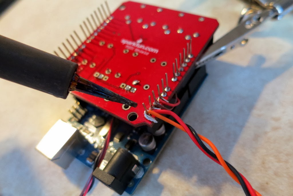
Assembling the Hardware: The MIDI shield comes as a kit that you need to solder together yourself, which is pretty direct and easy. After the shield was assembled, I then needed to attach my two audio jacks to convey the trigger signals out to my synths. Unfortunately, there are no solder holes on the Arduino or on the MIDI shield for attaching jacks or wires. So, I chose to solder some wires to the pins that connect the MIDI shield to the Arduino. Usually, this is not recommended approach, and you should be aware that it is a bit challenging to do (notice the tight space in the picture below) but it did work for me.
A kludge. I'm soldering the wires to my audio jack to the pins on
the MIDI Shield that will mate to the Arduino. Generally,
this is not recommended, but it works.
Once the wires are attached to the MIDI shield, then you just have to attach the jacks to the other end of the wires. As shown in the picture below, soldering to the jacks is much easier.
Soldering the wires onto the audio jack. These don't carry audio.
They carry the CV Trigger signals.
Finally, once all of the soldering is done, you simply mate the MIDI shield to the Arduino. The hardware is done!
My fully-assembled device for converting MIDI Clock to CV Triggers.
Writing the Basic Software: For the Arduino, I wrote some software that listens for the messages coming in from the MIDI port. MIDI is quite general (it's not just about keeping time) so my Arduino is programmed to ignore most of the traffic on the MIDI bus. It is listening solely for MIDI Beat Clock messages (ie, code 0xF8). The MIDI standard says that there should be 24 of these messages arriving for every quarter note. So, if I want a 16th note arpeggiation, and since a 16th note is a 1/4 of a quarter note, I programmed the Arduino to issue a trigger pulse after every 6 MIDI clock messages (because 24 * 1/4 = 6). To actually issue a "trigger pulse", the Arduino briefly raises (or lowers) one of its digital output pins. That's the trigger signal. That's all it takes!
Adding Fancy Features: Once I had the basic software working, I started adding features. First, because some arpeggiators like upward-pulses and other like downward-pulses, I wrote the software to do both. That's why I use stereo jacks for my outputs...the "left" channel is upward going while the "right" is downward going. The next feature that I added is a second set of trigger outputs to drive a second arpeggiator (hence my inclusion of the second audio jack). Then, to be adjust the speed of the arpeggiators relative to the MIDI clock (do I want 16th notes? 8th notes? whole notes?), I program the Arduino to read the two potentiometers and to set the MIDI clock divider (that number "6" discussed in the paragraph above) to make the triggers come faster or slower. This is pretty sweet.
Sharing My Software: I case anyone is interested, you can get the latest version of my MIDI-to-Trigger Arduino software at my GitHub, which is here. If you make improvements, send me a pull request!
Trying it Out: So, for my initial trials, I kept the setup simple. My Korg Kaossilator is going to be my drum machine. I'm going to have it drive the arpeggiator on my Mono/Poly. So, as shown in the figure below, I connected the Kaossilator's "MIDI Out" to the "MIDI In" on the Arduino MIDI-to-Trigger Converter. Then, I connected a cable from one of my converter's outputs to the "Arpeggiator Trig In" jack on the back of my Mono/Poly.
You can see the connections to my MIDI-to-Trigger converter in the photo below.
Connections to my MIDI converter. The Kaossilator is coming in via the MIDI
cable on the top left o the device. The Mono/Poly (off screen) arpeggiator
trigger is driven by the 3.5mm audio cable on the bottom of this picture.
As seen in the picture below, with all of these extra wires running around, the setup gets a little messy.
Zooming out to see the whole setup. Wires everywhere!
Once it was all connected together, I started some drum loops on the Kaossilator. Then I activated the arpeggiator on the Mono/Poly, I set it to "Latch", and then I locked in a few notes. And then nothing happened. After chasing down a couple of bugs in my software, I tried again. And then again. And eventually, I got it to work. The arpeggiator was stepping in sync with the Kaossilator. It was glorious. As shown in the video at the top of this post, I can change tempo and it all keeps going in sync. It's pretty fun.
Next Steps: The next steps are to run the arpeggiator on my Mono/Poly and the one on my Polysix at the same time. That'll be a really fun. Look for a follow-on post!
As many of you may be aware, I've modified my Korg Polysix by replacing the Key Assigner CPU with an Arduino. This means that I have a lot of control over how the Polysix manages its voices and pitches, which is how I could do things like add portamento, detuning, and single-trigger mode. Well, having such control over the voices has let me add a new operating mode, "Poly-Unison" mode. This mode assigns two voices for each note received from the keybed instead of just one voice. As a result, the Polysix feels a bit like the richer-sounding dual-oscillator polysynths that came before. It's fun! Check it out!
Background: Normally, in "Poly" mode, the Polysix has six voices, but each voice only has a single-oscillator. This is in contrast to fancier polysynths such as the Prophets, the Oberheims, and the Roland Jupiter polysynths that all had two oscillators for each of their voices. The dual oscillators give each voice a richer sound. The Korg Polysix and the Roland Juno series moved to single-oscillator voices to save money to make the synths more affordable, but at the expense of less rich sound. To add some richness back into the sound of these single-oscillator synths, Korg and Roland added Chorus and other effects. While these effects helped, the sound was still not as complex and "alive" as the dual-oscillator synths. I wanted to see what the Polysix might sound like if its voices had dual-oscillators. So, I pursued this "Poly-Unison" modification.
All Software: Given that I had already performed some major hardware modifications by adding the Arduino and the DAC to enable arbitrary voice and pitch management within my Polysix, the creation of this "Poly-Unison" mode was simply a software modification to my Arduino software. The concept is simple: whenever a new note is received from the keybed (or MIDI) start two of the Polysix's voices instead of one. That's pretty straight-forward.
User Interface: One challenge is figuring out how to use the limited number of controls on the Polysix's control panel to activate the new mode. I chose to re-use the existing buttons to look for a combination key press of the "Poly" and "Unison" buttons, as shown below. The baseline behavior is like with an unmodified ("stock") Polysix. Press-and-release the "Poly" button to get Poly mode or press-and-release the "Unison" button to get Unison mode. For my new mode, press-and-hold the "Poly" button and then press-and-release the "Unison" button to get the Poly-Unison mode. The lights show up properly to indicate the new state.
Detuning: Simply enabled my Polysix to assign two voices to each note is not fully capturing the functionality of the dual-oscillator polysynths of the past. A key feature of having two oscillators is being able to detune one oscillator relative to the other. It is the detuning between the two pitches that gives each note the richness that so many people like. To make this Poly-Unison experiment a success, I need to be able to detune the voices. Luckily for me, I had already added adjustable detuning to my Polysix's Unison mode. It was a small software change to enable detuning to my Poly-Unison mode.
User Interface for Detuning: In my previous post discussing detuning, I mentioned how I re-used the Polysix's "Arpeggio" button to control the detuning. Below is a more-full explanation. First, to activate detuning, simply press and release the "Arpeggio" button. Fine. To increase or decrease the amount of detuning, press-and-hold the "Arpeggio" button and then turn the "Speed" knob. Since the "Arpeggio" and "Speed" controls are so close, you can do it with one hand while still playing the keyboard with the other hand. As you can see in the video at the top of this post, it works pretty nicely. To deactivate the detuning, simply press-and-release the "Arpeggio" button again. It'll remember the detune setting the next time that you activate the detuning.
But What About the Arpeggiator? You might wonder, if I'm using the "Arpeggio" button for detuning, how do I activate and deactivate the Arpeggiator? The answer is that I repurposed one of the two little switches on the back of the Polysix to be a kind of "mode" switch for my control panel. Specifically, I'm using the "High/Low" switch that controls the sensitivity of receiving data "From Tape". Since I don't use this feature, i rewired this switch to connect to my Arduino. When set in one position, it tells my Arduino to listen to the Arpeggiator controls normally -- as controls for the Arpeggiator. When set in the other position, it tells my Arduino to listen to the Arpeggiator controls as commands for detuning, portamento, and aftertouch. It's a pretty nice little system!
Next Steps: As you can see in the video, the Poly-Unison mode works pretty nicely. In this setup, two voices are assigned to each note. In this mode, each of the two voices is playing the same note. The next step would be to do a Poly-Chord-Memory mode where two voices are used, but they could be set to different notes. That would be cool, too!
Another next step would be to enable "oscillator sync" between the linked voices. That would really bring my Polysix into line with the features of the old two-oscillator polysynths. But, I'm not really sure how to do that, and I think that it would require some tricky hardware changes. Any suggestions?
Inspired by Adafruit's Electronic Halloween, and in particular Becky Sterns "Space Face" and "Firewalker LED Sneakers", I decided that I had to make something light up this Halloween (and maybe wear some make-up, too). Here's what I came up with:
While the video above simply has the LEDs oozing through the rainbow colors (straight out of Adafruit's example code for the LED strip), my hat was also equipped with a bunch of sensors to allow it to respond to the world around it. Check out the two other operating modes below:
So, you can count me as one of the multitudes of folks adding LEDs to hats for good fun at parties! It may be simple, but it's SO MUCH FUN!
Interested in making your own world-responding LED hat? Well, below are a couple pictures showing some details on how I put it together.
The most expensive thing on my list is the Mongoose. I happened to have one that I harvested from an old project. It's nice and small and has all those cool sensors...but it's pricey. If you don't want to spend the money for that, you could use a regular Arduino. That will let you do pre-programmed LED effects (like the rainbow effect shown in the first video). And that would be totally cool just by itself. If you do want to add the ability to be sensitive to motion (like I did), you can still avoid the Mongoose by using a regular Arduino paired with one of those accelerometer / magnetometer combo sensors. You could try this one from Adafruit. I think that would work just fine.
One of the hardest parts for me was figuring out how to attach it all to the hat. So, on my wife's very good suggestion, I used a little twine to tie the battery pack through the holes in the wicker hat and loops of thread to "sew" the LED strip to the hat at select locations. Easy! And, it was surprisingly effective. (Maybe that's because my wife also helped greatly in actually doing the attaching!)
So, that's my story. It was a great hat. It was also (for me) a fun make up job. Another set of thanks go to my talented make-up artist, Ange!
As a follow-up to this post, my first PCB has arrived from the printer! She's a beauty (to my eyes, at least)...and so tiny!
I used my multi-meter to ensure that all the connections go where they are supposed to go, and to confirm that the connections do not go where they are not supposed to go. It looks like it's time to solder in the components and give it a go!
(Note, this'll also be my first time soldering surface-mount components...I designed the board with one SMT cap on the front and one SMT cap on the, just to give me a reason to give SMT soldering a try. I'm hopeful!)
Follow-Up: I finally assembled the PCB. Check it out here!
Sometimes, when you're away from home but still need the feel of some synth keys under your fingers, you just gotta go with whatever available locally.
The Classic Casio SA-76.
So I'm attending a conference in Boston. I'm staying at a friend's house. I didn't bring any of my synths (I mean, really, traveling to a non-music conference with one's synth would be a little silly). The chaos of the traveling and of the schmoozing and meetings has made me uptight. I need to chill-out, I need to relax. But I got nothing with me...no keys, no musical instruments of any kind. What to do?
Well, being a Renaissance Man (and his lady being a Renaissance Lady), my friends are raising their very young children delightfully, with full engagement with language and nature and arts and music. So, while their young ones might still be a bit small for a proper Moog, they are not too small for the timeless power of an all-in-one Casio. As can been seen, their particular Casio SA-76 is clearly Hello Kitty approved.
Looking at this synth, you might not be impressed. Sure, the keys on this smokin' axe might be miniature, but my joy in having something -- anything -- to calm my traveler's nerves was anything but miniature. Each one of its 26 little ivories and 18 little ebonies was a tender salve to my travel pains.
The Key to Casio Appeal...the Backing Beats.
We all know that the draw of a classic Casio is the depth of its pre-programmed beats. And I was not disappointed. Oh, "POPS", who knew that if you dropped the Casio's Tempo down to "4", your kicks would thump and your hi-hats would snap in such Hip-Hop-Horray that my stresses would be forgotten.
Then, by incrementing the pattern (#5, yes #5!), speeding the beat a bit, dialing in a tasty organ, who knew that the Casio would become a magical teleportation device delivering me to my musical happy place. And who knew that, on that day at least, my musical happy place would be Rockin' the Casio!
I've done it. I've made the leap. I've designed my first PCB. Yay!
Top and Bottom Illustrations of my PCB (from OSH Park)
The purpose of my new PCB is to be a breakout board for the MCP4922 DAC. This is a 2-channel, 12-bit DAC that I've used for previous projects including: (1) a pitch CV quantizer for my theremin, (2) a pitch CV corrector for my ribbon controller, (3) a CV recorder/looper for my Korg Mono/Poly, and (4) an Arduino wavetable oscillator. It's this latter project -- the wavetable oscillator -- that I'm looking to resurrect.
I'm eventually looking to make six of these wavetable oscillators -- one for each voice of my Korg Polysix. On my previous projects, I just wired up each DAC individually by hand on some proto-board. But, when making six, that's just too full of error possibilities. So, I designed my first PCB to simplify the construction of six units. This simple first board will be a stepping stone to my actual goal, which is to build a bigger board that includes two of these DACs (permitting 4 channels of audio and/or CV outputs) along with an Arduino-compatible AVR microcontroller to drive the DACs. All of this will be on one PCB. For a guy who has never designed a PCB before, I figured that it would be better to start smaller...such as with this MCP4922 breakout board.
Schematic that I Created in Eagle 6.5
For software to do the PCB design, I chose to use CadSoft Eagle. I hear that Design Spark might be a better choice (also free, but with fewer constraints than Eagle), but most of the bigger DIY electronics sites (Sparkfun, Adafruit) seem to provide their designs and models in Eagle, so I went with that.
Any PCB design starts with defining the schematic for the circuit that you want to turn into a PCB. Since I'm just doing a breakout board, the schematic ought to be very simple since their are so few components. The primary elements are just the IC in the middle and some connectors (or through-hole solder points) around the periphery. As you can see in the schematic above, I all the input signals to the DAC come in via an 8-pin header on the bottom left (I only needed 7 pins, but the PCB model for the 8-pin looked better). As for the outputs of the DAC, I brought its two outputs to separate 2-pin headers, as shown on the right side of the schematic. Pretty straight-forward.
In addition to the connectors around the periphery, it is common for a breakout board to include those supporting components (capacitors and resistors) that are necessary for every likely usage of the chip. Looking at the chip's datasheet, I see that it always suggests that you use a couple of caps for power supply decoupling, so I included 0.1 uF and 10 uF capacitors in my design. Also, after looking through the datasheet, I decided that I was never going to want to change the reference voltages applied to the chip, so I just tied those pins to the power supply, which the datasheet said was fine.
The centerpiece of this design is, of course, the MCP4922 chip itself. Note that labeling on its symbol is poor ("REFDES TYPE", what is that?). The problem is either that I don't know how to use Eagle (which is true) or that the device model itself is poor because it was robo-translated to Eagle format from the generic format provided by Microchip. When I was done, I found a model for the MCP4922 in the Adafruit Eagle library. I should have used that version of the model instead. But, what's done is done.
2-Layer PCB Design as Performed in Eagle. Red traces are on the top layer. Blue are on the bottom.
After completing the schematic, I switched Eagle over to its PCB layout mode. With a friend's help on how to use the program, I whipped out the design above. Note that the traces use a few different widths...some are fat and some are skinny. The inconsistency is my fault and it is only partly by design. The default trace size is very thin. I thought it important that the power and ground traces be thicker, especially between the IC and the decoupling caps. So, I thickened those particular traces by hand. I did not do a great job. In the future, I'll try Eagle's "nets" feature so that the trace thickness is more automated.
You'll also note that everything on the PCB is through-hole, except for the two caps, which are SMT (surface mount). This will be my first time soldering SMT. Caps are pretty easy, so this should be good training for me. If it goes well, maybe I'll use more SMT for my future, bigger circuits.
After completing the PCB layout, I had to choose where to get the board manufactured. Being a fan of Sparkfun, I remembered one of their blog posts that talked about their BatchPCB service being merged with OSH Park. So, I checked out OSH Park and it looked like a pretty good deal (2-layer board for $5 per square inch, and you get three copies). A key benefit for me was that OSH Park allows you to upload your Eagle file directly, without going through the error-prone process of exporting Gerber files. For a newbie like me, that's outstanding.
Before sending my PCB design to OSH Park, I downloaded their DRU file for Eagle, which specifies all of the design limits used in their manufacturing process. This is important to ensure that your design can actually be fabricated. When I ran the DRU check on my PCB,Eagle reported some errors with my design. Mainly it saw that all of my "text" was assigned to the wrong layer. If I didn't change anything, my "text" was actually going to be printed copper traces on the same layers as the rest of my traces. This would have shorted everything out! Oops! Thank you DRU check! So, I corrected the problem by moving my text to the correct layer ("21" in Eagle) and re-ran the DRU check. Now everything was good.
I uploaded my design to OSH Park. After processing the Eagle file, the OSH Park page produces a bunch of images of my board (like the one at the top of this post) so that I could check the design. I noticed that some text was written wrong, so I fixed that in my Eagle file and uploaded the design again. I iterated like this 3 or 4 times before I was happy. When I was eventually satisfied, I accepted the design. It's going to be $5.85 for three copies and the shipping is free. What a deal!
Now I wait for them to arrive. And to see what design errors I made. Isn't this hobby fun!?!
(Oh, I shared my PCB design on OSH Park. If you're curious, you can see it here.)
Follow-Up: The PCB's have arrived! Check it out here.
Follow-Up: I've assembled the PCB. Check it out here.
Follow-Up: I've tested the PCB. It works! Yay! Check it out here.
Follow-Up: I've designed my second PCB. Much more complicated. You can check out the story here.