We all know that, given their age, most Korg Polysix's have problems. Usually, the problems are related to the dreaded "leaking battery" problem. My Polysix had that problem and I fixed it (I hope). My Polysix, though, also had a problem with the push-buttons being very finicky. I think that this is a common problem, too. I've replaced many (but not all) of the switches when I first got the synth. Recently, though, my "Arpeggio" button started acting up, so I decided to replace it. For anyone who needs to replace any of their buttons, here's a picture tour of the process. (By the way, the buttons on the Korg Mono/Poly are the same, so this applyies to Mono/Poly owners as well!)
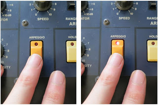 |
| I replaced the Arpeggio button and now it works great! |
The general outline for replacing one of the push-buttons is:
- Open the synth
- De-solder the old button and the associated LED leads
- Un-fasten the button's PCB from the synth
- Remove the button cover
- Remove the button itself
- Solder in the new button
- Re-attach the button cover and solder the LED leads
- Re-attach the button's PCB to the synth
- Re-fasten the PCB and close the synth
So, here we go with pictures and description and tips:
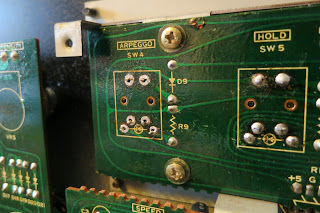
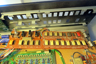
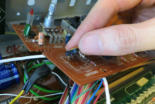
(1) Open the Synth: I don't have any pictures of this because it is pretty straight-forward. Unscrew the four screws on the cover panel and unscrew the four (?) screws on the bottom of the synth that secure the bottom lip of the cover panel. Once you've got the synth open, you've got to find the PCB holding your button. Since I'm replacing the Arpeggio button, it was pretty easy for me...they labeled it! Note that they spelled it "Arpeggo" (oops!), which amuses me. But, since we're talking about labels on PCBs, why are the labels in English? Wasn't this synth designed in Japan? Why aren't the labels in Japanese? I've never understood why there's so much English on circuit boards made throughout the world.
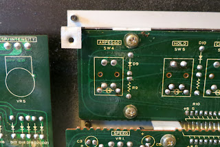 |
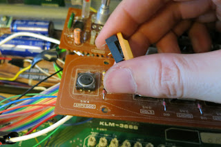
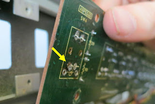
| Here's the back of the Arpeggio button. De-solder all six solder points. |
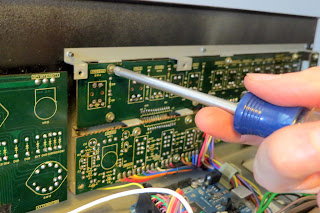
(2) De-Solder the Old Button and LED Leads: To de-solder the button, you'll note that there are six solder points. Four are for the legs of the push-button and two are for the LED that's built into the button cover. You'll need to de-solder all six. You can do this using
solder wick and/or a
solder pump. I used the pump for the bulk of the work (see
my earlier post for a bit more description) and I used the solder wick to wipe up (soak) up the little bit of solder that remained.
 |
| First, apply heat until the solder melts. |
 |
| Use the solder pump to suck out the molten solder. |
 |
| After a final touch-up with the solder wick, here's what it looked like. |
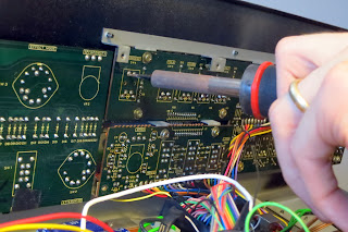
(3) Unscrew the PCB: To get the button off the PCB, you'll need to detach the PCB from the synth so that you can get access to the top of the synth. The PCB that holds the Arpeggio button has lots of screws. You need to remove them all. This particular PCB is also connected to two daughter PCBs. You'll need to unscrew those as well.
 |
| There are lots of screws to remove on this PCB ad its daughter boards. |
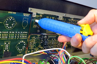
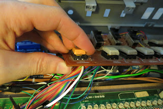
One of the daughter PCBs holds the potentiometer Arpeggiator Speed control. To free the PCB from the synth, you need to remove the plastic knob...just work your finger tips under the lip of the knob and pull it off. Then unscrew the nut that holds the potentiometer to the case. Easy.
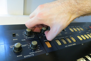 |
| For this PCB, you also need to remove the knob and the nut on the potentiometer. |
You'll notice that you've collected quite a few bits and pieces from your synth at this point. You've got screws from the synth's case, you've got screws from the PCB(s), and you've got the knob and nut from the potentiometer. Don't loose those bits! I have a set of little bowls that I use anytime that I remove items from my synth. If the bits go into the bowl, then I know where to find them when I go to re-assemble the synth. Any bits that remain in the bowl when I'm "done" are a reminder that I must have missed something. The bowl is critical!
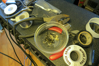 |
| I keep all of my screws and knobs in a little bowl while I work. |
And now the PCB is no longer secured. This particular PCB requires a little twisting and sliding, but eventually it comes from from the panel.
 |
| The PCB is free! |
(4) Remove the Button Cover: These push-buttons are composed a two main parts: the button itself and a button cover [*see comment section at bottom]. The button itself is what we need to replace. It lies under the button cover. The button cover is the colored plastic piece that you actually touch with your finger. The button cover also holds the red LED that lights up when you press the button. The button cover is what we need to remove first.
The button cover is held on to the PCB once the legs of the LEDs are soldered to the board. The button cover is also held on through friction with the button itself. To free the button cover, I generally use my soldering iron on the bottom of the PCB to push the leds of the LED up into the board (the soldering iron also melts any residual solder that might be holding the LED legs). At this point, I can generally wiggle or pry the button cover off the button. Once you do one, you'll have more confidence when you do others.
 |
| The button cover has been removed from the button. Notice the two legs of the LED sticking out of the button cover. |
(5) Remove the Button: The button itself is held to the PCB by its four legs. The legs are both soldered in place and they have a certain bend in their shape that helps them grab the board. You've already removed most of the solder, but there might be a little left in there. So, I again take my soldering iron and, from the bottom of the board, try to push each leg back into the PCB. I'm trying to push the button up off the board through pushing on its legs. I also use my needle-nose pliers to try to pry under the button while I'm applying the heat. Surely, there is a better way of doing this, but eventually I'm able to get the buttons off.
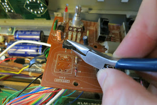 |
| Using a soldering iron and pliers, I eventually get the button off the PCB. |
(6) Attach the New Button: Before you solder the new button, you need to buy a new button. Via a post by Anon on the
Polysix Yahoo Group, I was pointed to some Omron 12mm x 12mm tactile switches that did the job. From Mouser, I ordered some Omron
B3F-4000 and some
B3F-4005 -- the only difference between the two being the amount of force necessary to activate the switch. Once installed in the synth, I couldn't really tell the difference between the two, so either is fine. The B3F-4005 is shown in the picture below.
 |
| An Omrom B3F-4005 P |
To mount the switch to the PCB, line of the legs of the button with the holes in the PCB. At this point, I usually get out the soldering iron (again) and heat the hole from the underside so that I melt any solder that might still be in the hole. I then push one of the button's legs part-way (or fully) into the hole. I then repeat for the other legs. Once all four legs are in the holes, I heat and solder from the bottom of the PCB like normal.
 |
| Lining up the legs of the button with the holes in the PCB. |
Unfortunately, because I'm no expert at doing this, I damaged the PCB when I pushed the legs through the hole. As can be seen in the picture below, I leg pushed one of the solder rings off the PCB. This is definitely the mark of an amateur. Lucky for me, all four legs of the switch are soldered into the circuit when only two are really needed....which means that there is redundancy! I can lose one of the connections (due to the lifted solder ring) and still have a good solid button. Lucky for me!
 |
| I lifted up one of the solder rings. Dang! |
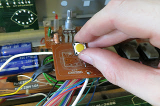
(7) Re-Attach the Button Cover: Once the button is soldered in, we can now re-attach the button cover. First, I line up the button cover with the button, including the legs of the LED with the holes in the PCB. I then push the legs of the LED through the PCB holes, usually with some heat from the soldering iron to melt any left-over solder that's in the hole. Once the legs are through the hole, I make sure that the button cover is fully-seated around the button itself. Then, on the bottom of the PCB, I solder the legs of the LED like usual.
 |
| Seating the Button Cover on the Button. |
(8) Re-Fasten the PCB and Close the Synth: The work with the button is now done. To finish, simply, re-fasten the PCB to the inside of the synth (do you still have all the screws?) and close panel of the synth (do you still have those screws, too?). Turn on the synth and enjoy your new button!
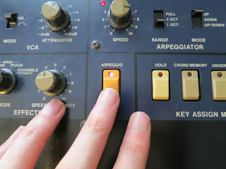 |
| The Button Now Works Great! |


I had a comment from backshall1 on the Polysix Yahoo Groups list who suggested: " I think it should more explicitly say that there are four parts, including the LED. The "button cover" is two pieces, the frame and the cap. The cap is the colored part (gray, beige, red, orange) and the frame is black. Make sure you mention to NOT try to remove the cap from the frame, as this usually results in breaking the little black plastic hinges that hold it on. You must remove the frame, cap and LED (three pieces) together, after unsoldering the LED." Great comment!
ReplyDeleteAnd then there was a very helpful follow-up comment by Syntegrator saying that replacement button covers could be had from http://syntaur.com/
DeleteThis comment has been removed by the author.
DeleteExcept for those button covers that Syntaur no longer has in stock, such as for the Casio CZ-1. See my comment/request below.
Deleteeasy as pie - but just make sure you desolder the two frame pins in the PCB first and the whole thing just 'comes off'
DeleteOne more helpful comment:
ReplyDeleteFor those who prefer to install a (supposedly) longer lasting version of this button, Mouser also sells this one:
Mouser Part #: 653-B3F-5000
Manufacturer Part #: B3F-5000
http://ca.mouser.com/ProductDetail/Omron/B3F-5000/?qs=%2fha2pyFaduikx5xSkGOJUJoXlIjxCDfnWT5ovGJDJMMuLPoO5vYxvQ%3d%3d
It is described as "Lg Svc Life" (Long Service Life)
It is slightly more expensive ($0.54 instead of $0.40) but will hopefully last longer and save you some work later.
It is also a 130 g. Operating Force button
and has Silver Contact Plating.
By the way...
Thanks for all your contribution!
I really enjoy reading your blog and using it as a reference.
Keep up the great work!!!!
-SynthOSphere
What about replacing the actual plastic button cover? For any synth that is missing the actual button from the faceplate, I was thinking of making a latex mold of an existing button but don't know what plastic to use to make the replacement button, or if it should be epoxy, or how to get it the same color as the original, or how to put any marking into it like words or arrows so they don't wear off after time. I have not found any info on this searching the web. Any advice would be welcome.
ReplyDelete