We all know that, given their age, most Korg Polysix's have problems. Usually, the problems are related to the dreaded "leaking battery" problem. My Polysix had that problem and I fixed it (I hope). My Polysix, though, also had a problem with the push-buttons being very finicky. I think that this is a common problem, too. I've replaced many (but not all) of the switches when I first got the synth. Recently, though, my "Arpeggio" button started acting up, so I decided to replace it. For anyone who needs to replace any of their buttons, here's a picture tour of the process. (By the way, the buttons on the Korg Mono/Poly are the same, so this applyies to Mono/Poly owners as well!)
I replaced the Arpeggio button and now it works great!
The general outline for replacing one of the push-buttons is:
Open the synth
De-solder the old button and the associated LED leads
Un-fasten the button's PCB from the synth
Remove the button cover
Remove the button itself
Solder in the new button
Re-attach the button cover and solder the LED leads
Re-attach the button's PCB to the synth
Re-fasten the PCB and close the synth
So, here we go with pictures and description and tips:
(1) Open the Synth: I don't have any pictures of this because it is pretty straight-forward. Unscrew the four screws on the cover panel and unscrew the four (?) screws on the bottom of the synth that secure the bottom lip of the cover panel. Once you've got the synth open, you've got to find the PCB holding your button. Since I'm replacing the Arpeggio button, it was pretty easy for me...they labeled it! Note that they spelled it "Arpeggo" (oops!), which amuses me. But, since we're talking about labels on PCBs, why are the labels in English? Wasn't this synth designed in Japan? Why aren't the labels in Japanese? I've never understood why there's so much English on circuit boards made throughout the world.
Here's the back of the Arpeggio button. De-solder all six solder points.
(2) De-Solder the Old Button and LED Leads:To de-solder the button, you'll note that there are six solder points. Four are for the legs of the push-button and two are for the LED that's built into the button cover. You'll need to de-solder all six. You can do this using solder wick and/or a solder pump. I used the pump for the bulk of the work (see my earlier post for a bit more description) and I used the solder wick to wipe up (soak) up the little bit of solder that remained.
First, apply heat until the solder melts.
Use the solder pump to suck out the molten solder.
After a final touch-up with the solder wick, here's what it looked like.
(3) Unscrew the PCB: To get the button off the PCB, you'll need to detach the PCB from the synth so that you can get access to the top of the synth. The PCB that holds the Arpeggio button has lots of screws. You need to remove them all. This particular PCB is also connected to two daughter PCBs. You'll need to unscrew those as well.
There are lots of screws to remove on this PCB ad its daughter boards.
One of the daughter PCBs holds the potentiometer Arpeggiator Speed control. To free the PCB from the synth, you need to remove the plastic knob...just work your finger tips under the lip of the knob and pull it off. Then unscrew the nut that holds the potentiometer to the case. Easy.
For this PCB, you also need to remove the knob and the nut on the potentiometer.
You'll notice that you've collected quite a few bits and pieces from your synth at this point. You've got screws from the synth's case, you've got screws from the PCB(s), and you've got the knob and nut from the potentiometer. Don't loose those bits! I have a set of little bowls that I use anytime that I remove items from my synth. If the bits go into the bowl, then I know where to find them when I go to re-assemble the synth. Any bits that remain in the bowl when I'm "done" are a reminder that I must have missed something. The bowl is critical!
I keep all of my screws and knobs in a little bowl while I work.
And now the PCB is no longer secured. This particular PCB requires a little twisting and sliding, but eventually it comes from from the panel.
The PCB is free!
(4) Remove the Button Cover: These push-buttons are composed a two main parts: the button itself and a button cover [*see comment section at bottom]. The button itself is what we need to replace. It lies under the button cover. The button cover is the colored plastic piece that you actually touch with your finger. The button cover also holds the red LED that lights up when you press the button. The button cover is what we need to remove first.
The button cover is held on to the PCB once the legs of the LEDs are soldered to the board. The button cover is also held on through friction with the button itself. To free the button cover, I generally use my soldering iron on the bottom of the PCB to push the leds of the LED up into the board (the soldering iron also melts any residual solder that might be holding the LED legs). At this point, I can generally wiggle or pry the button cover off the button. Once you do one, you'll have more confidence when you do others.
The button cover has been removed from the button. Notice the two legs of the LED sticking out of the button cover.
(5) Remove the Button: The button itself is held to the PCB by its four legs. The legs are both soldered in place and they have a certain bend in their shape that helps them grab the board. You've already removed most of the solder, but there might be a little left in there. So, I again take my soldering iron and, from the bottom of the board, try to push each leg back into the PCB. I'm trying to push the button up off the board through pushing on its legs. I also use my needle-nose pliers to try to pry under the button while I'm applying the heat. Surely, there is a better way of doing this, but eventually I'm able to get the buttons off.
Using a soldering iron and pliers, I eventually get the button off the PCB.
(6) Attach the New Button: Before you solder the new button, you need to buy a new button. Via a post by Anon on the Polysix Yahoo Group, I was pointed to some Omron 12mm x 12mm tactile switches that did the job. From Mouser, I ordered some Omron B3F-4000 and some B3F-4005 -- the only difference between the two being the amount of force necessary to activate the switch. Once installed in the synth, I couldn't really tell the difference between the two, so either is fine. The B3F-4005 is shown in the picture below.
An Omrom B3F-4005 P
To mount the switch to the PCB, line of the legs of the button with the holes in the PCB. At this point, I usually get out the soldering iron (again) and heat the hole from the underside so that I melt any solder that might still be in the hole. I then push one of the button's legs part-way (or fully) into the hole. I then repeat for the other legs. Once all four legs are in the holes, I heat and solder from the bottom of the PCB like normal.
Lining up the legs of the button with the holes in the PCB.
Unfortunately, because I'm no expert at doing this, I damaged the PCB when I pushed the legs through the hole. As can be seen in the picture below, I leg pushed one of the solder rings off the PCB. This is definitely the mark of an amateur. Lucky for me, all four legs of the switch are soldered into the circuit when only two are really needed....which means that there is redundancy! I can lose one of the connections (due to the lifted solder ring) and still have a good solid button. Lucky for me!
I lifted up one of the solder rings. Dang!
(7) Re-Attach the Button Cover: Once the button is soldered in, we can now re-attach the button cover. First, I line up the button cover with the button, including the legs of the LED with the holes in the PCB. I then push the legs of the LED through the PCB holes, usually with some heat from the soldering iron to melt any left-over solder that's in the hole. Once the legs are through the hole, I make sure that the button cover is fully-seated around the button itself. Then, on the bottom of the PCB, I solder the legs of the LED like usual.
Seating the Button Cover on the Button.
(8) Re-Fasten the PCB and Close the Synth:The work with the button is now done. To finish, simply, re-fasten the PCB to the inside of the synth (do you still have all the screws?) and close panel of the synth (do you still have those screws, too?). Turn on the synth and enjoy your new button!
Dear Readers, I'm sorry. Back when I described how I prepared my new keybed for installation into my Korg Polysix, I made it sound fairly straight-forward with no real hiccups. Sure, at the end, I mentioned something about how a couple of capacitors might have been a little too tall, but this was actually quite a large understatement. It turns out that those "too tall" capacitors required that I boost up the keybed even further than shown originally, which then prevented the Polysix's control panel from closing. It was ugly and frustrating and disheartening. Here's a description of how I fixed the problem.
Here Are the Offending Capacitors That Interfere with the Keybed
As you can see in the picture above, there are two groups of offending capacitors. Both sets of caps happen to be on KLM-366. The first group are the six tall Mylar caps (C31-C36) that are part of the "hold" circuits between IC29 and IC25. The second group of interfering caps include the tall Mylar cap C23 and the stout electrolytic cap C22, both of which are part of the pitch-correction feedback circuit. At first, I thought that the solution might be to replace all the caps with smaller ones (such as ceramics). But after a brief exchange with the Polysix Yahoo Group, I considered alternate approaches. With fresh eyes, it seemed like the best plan was to simply bend over the capacitors so that they weren't as tall. Easy!
Could I Just Tip the Capacitors to the Side to Make Them Less Tall?
Unfortunately, the caps were mounted very close to the PCB and didn't have enough of their leads above the board to enable me to tip them over. Since I just replaced an IC on this PCB, though, I have the synth all apart and, therefore, I have full access to the bottom side of KLM-366. Looking closely, I saw that each cap had a little bit more of its legs sticking out below the PCB. So, I got out my soldering iron, I applied some heat to the tips of the legs until the solder melted, and then I pushed until I couldn't see the tips of the legs anymore. See the picture below.
Looking at the Underside of the PCB. Making the Caps Taller By Pushing on the Tips of their Legs.
Once I did this, the first cap was now taller than it had been because of the extra bit of each leg that I pushed back above the PCB. Now it was tall enough that I could tip it over with ease.
Bending Over Worked well for the First Cap. Now for the rest...
After repeating the process for the remaining five capacitors, things are looking pretty good. Now it's time for the other two caps.
The Six "Hold" Caps Are Done. Now It's Time for C22 and C23.
The tall Mylar cap on the left side of the picture above was easy to address -- I simply did the same trick of re-heating the solder joint and pushing up the extra bit of each leg. Then, I bent him over. The electrolytic cap, though, was too stout (too fat) to push over. Having a bunch of electrolytic caps on hand, I decided that it would be easier to just replace this guy with one that was skinnier and that had long enough legs to bend over. So, I de-soldered the old one and soldered in the new one. I bent it over and, as you can see below, everything is shorter than it was before.
All the Caps are Now Much Shorter Than Before.
With all of the steps complete, I put the keybed back into the synth. Did it fit? Well, the part of the keybed that was near the caps fit great. That problem was solved. But, with that part of the keybed sitting correctly, it now revealed that another part of the keybed was interfering with something within the case of the Polysix. A little poking around showed that the long white bar of plastic that I added to my keybed wanted to sit right on top of the rail that holds the whole front side of the KLM-366 and KLM-367 boards. That's an easy fix that I'll talk about later (just cut that darned plastic bar!). For now, though, we can be content that this cap-bending job was the key. It was the key to enabling the keybed to sit properly in the Polysix's case and for the lid to close properly and for the whole thing to be beautiful. Ah...joy...
So far, I've been pretty successfull with hacking aftertouch, portamento, and detuning into my Korg Polysix . My next big goal is the addition of velocity sensitivity, which requires me to better understand the VCF control circuitry on KLM-366. Well, in probing the clock signals for the VCF multiplexing, I killed my Polysix! This is the story of how I brought her back to the land of the living.
Probing IC12 on KLM-366. I think that I've found the problem.
How Did I Kill It? This all started when I was probing around the part of the KLM-366 board that processes the VCF EG signal for each voice. Specifically, I was exploring the time-division multiplexing of the VCF EG through IC24 and IC23 . This multiplexing is all kept in sync via clock signals "A", "B", "C", and "INH" that are generated from IC11 and IC12 (schematic below). In probing IC12, I accidentally shorted one of the pins on IC12 (likely pin 11), which apparently killed it. As you can see in the pictures above, the "B" signal is clearly bad (it is supposed to be a square wave pulse).
How Do I Fix It? Replacing IC12 seemed like the only reasonable answer. The chip itself is really cheap (68 cents). The hardest part in replacing the IC is disassembling the synth so that I can get good access to the circuit board. I don't like taking it apart because it gives me too many opportunities to loose screws and to re-connect connectors in the wrong place and stupid stuff like that. But, in this case, I think that it needs to be done.
Shopping List: The only part that I really needed was a replacement 14024 chip. Like usual, I got it from Digikey. The specific part that I bought was MC14024BCPGOS-ND. I chose this part because (I think) it is the only through-hole version of the 14024 that they sell. At 68 cents, I bought 2, just in case I damaged one during my installation. Also, following the advice from The Old Crow, I decided to install an IC socket at IC12 in order to ease any future replacement of this chip. There are tons of choices for sockets. Never buy the cheapest ones. I liked the look of A32869-ND. Even though it was only 78 cents, it seemed to be one of the higher end models. Cool.
Removing the Dead IC. The replacement process starts by removing the dead chip. Some helpful folks at my workplace suggested that removing an IC is best done by first snipping off each of its legs so that the body of the IC just falls free of the PCB. Then, as long as you snipped the legs high enough away from the board, there's plenty of leg left to grab with your pliers so that you can apply a little heat and lift each leg out one-by-one. Pretty easy.
Snip Each Leg of the IC
All Legs Are Snipped, The Body is Loose, and the Legs are Still in the PCB.
Removing Each Leg from the PCB.
Removing the Old Solder: Even after removing the IC's legs, there was lots of old solder that is plugging the holes in the PCB. In order to get the new IC socket into all those holes, it's usually best to remove that old solder. There are a few ways that you can do this -- solder wick and a solder pump being the two most common. Clearing plugged through-holes is a perfect task for a solder pump. With a solder pump, you first apply your soldering iron to the hole until the solder melts. Then, you quickly put the spring-loaded solder pump over the hole and, while the solder is still melted, you hit the release button. BANG! The pump pops open and (hopefully) sucks out the liquid solder. Because I'm new to this, I usually had to try 3-4 times before I got the solder out. As you can see below, the holes looked fairly clear when I was done.
Using a solder pump to suck out the solder from the holes.
The holes are now fairly clean and ready for the new IC (or socket).
Installing the IC Socket: At this point, I was able to insert my new IC socket into the holes in the PCB (see below). It fit pretty nicely. Now I just needed to solder it in. Unfortunately, one really needs access to the bottom of the PCB to do this, which means the synth needs to be partly disassembled. So, I removed the keybed, I removed the rail holding down the PCBs, and I unscrewed all the screws holding down the PCB. I then removed a few (but not all!) of the multi-pin connectors so that I could tip up the PCB and get access to the bottom (see pic below...the power drill is holding the PCB upright). Once I was able to access the bottom of the PCB, I was soldered the legs of the IC socket to the PCB. We're cooking right along now! Smell the solder!
Inserting the IC Socket. It fits!
Getting access to the bottom of the PCB.
Soldering the legs of the IC Socket. Heat the site and THEN apply the solder.
Finishing Up: Once the socket was soldered in, I layed the PCB back down and I inserted the replacement 14024 IC into the new socket (see pic below). I then re-attached all the connectors that I had undone, I double checked that I re-connected everything correctly, and I turned on the power. With the oscilloscope, I checked the "A", "B", and "C" clock signals being generated by the new 14024 (see pic below). Everything seems to work!
The replacement 14024 IC is nestled into its new home on my KLM-366.
After Replacing IC12, the clock signals all look good.
Oh, The Joy: With the circuit looking like it's working again, I re-attached the keybed, closed the lid, and fired her up. Here's my little jam of joy...the playing is crappy, but it's so good to hear her voice again.
In the process of adding detuning to my Korg Polysix, I spent a bit of time looking in detail at the detuning on my Korg Mono/Poly. I've always liked the sound of the Mono/Poly's 4-voice unison with the Detune knob cranked up a bit. So, as I was setting up the detuning functions on my Polysix, I looked at the detuning on my Mono/Poly to act as a guide. This is the story about what I found...
Mono/Poly VCO2 with Maximum Detuning -- Flat by 30-35 cents.
I started my investigation experimentally. I put the Mono/Poly in Unison mode and locked in a "C" using the Hold button. Using each voice's Level knob, I listened to the pitch of each voice by itself. By turning the Detune knob, I could hear what the detuning did to each voice. To my surprise, the Detune knob had no effect on VCO1 or VCO3 -- it only affected VCO2 and VCO4. At this point, if you look at the block diagram in the Mono/Poly service manual (see the figure below), it clearly shows that Detuning only affects voice 2 and 4. I had never noticed this before. I found it to be an interesting design choice by the Korg engineers.
Block Diagram from Mono/Poly Service Manual. Detuning is only on VCO2 and VCO4.
My next goal was to quantify the amount of detuning that is generated by the Mono/Poly. Looking at the schematic (see the bottom of page for the KLM-357 PCB), the circuitry involved with distributing and scaling the detuning control signal is too complicated for me to figure out quickly. So, instead, I returned to my experimental approach and just measured the out-of-tuneness generated by the detune knob.
Mono/Poly VCO4 with Maximum Detuning -- Sharp by 20-25 cents.
I found that with the Detune knob set to maximum, VCO2 was driven flat by 30-35 cents and that VCO4 was driven sharp by 20-25 cents. While it's somewhat interesting that the pitch deviations are slightly different for the two VCOs, I'm thinking that the difference is not purposeful and is actually just due to imprecision in the circuit components. What I think is more interesting is that they chose to do a balanced de-tuning with one voice driven sharp and another voice driven flat. Taken as an ensemble, therefore, the overall pitch of the four oscillator cluster is basically unchanged for any setting of the Detune knob.
Compare this approach to your more typical 2-oscillator-per-voice monosynth or polysynth. Whether it's an old Minimoog or a Prophet-5, it is my impression that detuning is usually effected by changing the pitch of just the 2nd oscillator while leaving the 1st oscillator at the original pitch. If this is true, it means that the ensemble of the two voices together is always a bit sharp or a bit flat. Since these other synths are wonderful instruments and people love them, this unbalanced detuning must be an acceptable approach...but I've always felt that the detuned sound of the Mono/Poly just felt more "right". So, in adding detuning to the Polysix, I chose to use the balanced detuning approach.
Due to the limited number of knobs and switches on the Polysix that are seen by my replacement Key Assigner (ie, my Arduino), I don't have a knob that I can dedicate to the Detune function. Instead, I'm going to use a push button to turn the Detuning "on" with some default detuning factor. I did include a method to adjust the amount of detuning (a complicated press-the-button-while-turning-the-knob combination), but I'd like to get the default detuning correct so that adjustments are usually unnecessary.
How much detuning to I want to be my defualt? On the Mono/Poly, when i'm really getting the party started, I like to set the Detune knob to 5-6, which is 50%-60% of the total amount of detuning available on the Mono/Poly. Given that full detuning is (take the average of VCO2 and VCO4) is about 27 cents, my target detuning amount for the Polysix should be about 14-16 cents. The Polysix has six voices to detune, so I chose to detune two voices by 14-16 cents (one sharp and one flat), two voices by 7-8 cents, and two voices were left unchanged. I then coded these values into my detuning routines on my Arduino and, as you can see below, I got 15-20 cents...pretty darned close to my 14-16 cents target!
Detuning Amount on my Polysix...about 15-20 cents. Just what I wanted!
Like you can see in my demo video, the detuning works well on the Polysix -- I find the sound very engaging. My experience with the Mono/Poly was really helpful in tweaking the detuning so that it sounds right. Thank you Mono/Poly!
After adding the hardware and software to implement aftertouch vibrato and portamento, I realized that I could command the Polysix to do all sorts of arbitrary pitch-manipulation effects. With just a little bit of additional software, I could do pitch bends, pitch wobbles, pitch slides (hence the portamento), pitch transposition, or...wait for it...pitch detuning. I love the detuned unison sound on my Mono/Poly and now I can get it on my Polysix!
It should be noted that the Polysix already has a little detuning purposely built into its Unison mode. The circuit below is on the KLM-366 PCB and is only active in Unison mode. Via voltage dividers (R120-R122 per voice combined with R116 for all voices), this circuit generates a small voltage that is used to shift the pitch of each voice to be a little sharp or a little flat.
Polysix's Built-in Detuning Circuit for the Unison Mode
By looking at this piece of the schematic, it looks like this circuit leaves Voices 1 and 6 unchanged. It appears to shift Voices 2-4 up or down by between 16 and 33 mV. The schematic says that the pitch scale is 5V/oct at this point, so the per-voice pitch detuning is about 4-8 cents (4-8% of one half step). While that's enough to give a nice little swirl to the Unison mode, it doesn't give that meaty, fat detuned sound that has become popular in some electronic dance music styles. I intend to change that.
In terms of approach, one could simply modify the existing circuit. By replacing R116 with a bigger resistor (say 400-600 ohms), the detuning would get much more intense. It would still be a fixed amount of detuning, but it would be a very easy modification. The down side is that it is not adjustable (unless you wired in a potentiometer) and that it only applies to Unison mode -- it is not usable by Chord Memory mode.
Since I already have my Polysix modified with an Arduino and a digital-to-analog converter (DAC), I can do arbitrary pitch shifts and pitch bends on a per voice basis in any of the Polysix's modes of operation. That's a lot of pitch-mangling power. So, I wrote a little bit of software that, when I commanded the Arduino to effect "Detuned Mode", it would command a slight pitch shift to each of the Polysix's voices. How much pitch shift per voice?
Well, following from the Polysix's built-in detune, I left two of the voices at normal pitch and bent the other voices in pairs (one up, one down) to different degrees. The overall scale factor for the detuning I left as a variable that I could adjust on-the-fly so that I could control how much detuning I wanted.
Spectrogram of Output of Polysix While Adjusting the Amount of Detuning
For my user interface, I've temporarily mapped "Detune Activate" to my Polysix's arpeggiator button. Pressing the arp button activates or deactivates the detuning. Then, I can control the amount of detuning by holding down the arpeggiator button and turning the arpeggiator's "speed" knob. My Arduino sees the button being held and sees the knob being turned and interprets that as a command to adjust the detuning. It works great! The spectrogram above really shows how the voices spread apart as the amount of detuning is increased.
How does it sound? Well, the video is a demo of the audio coming out of my modified Polysix. At the very beginning, you hear me load up the six voices playing the same note. I lock in the six voices using the Chord Memory button. You hear that the voices are in pretty good unison. Then you hear me kick in the detuning. I like it a lot. Yes. A lot.
Getting aftertouch and portamento hacked into my Korg Polysix felt like a pretty good achievement. Now comes the part where I tune their response so that they feel just right. Last time, I spent some time adjusting the feel of the aftertouch. This time, I'm tuning the feel of the portamento. Specifically, I'm stealing some ideas from my Korg Mono/Poly to make the portamento more exciting and more engaging.
When I first implemented portamento, I coded it up as quickly as I could, which meant that I kept it as simple as possible. I wrote a nice pitch-slurring portamento function for my Arduino key assigner, the core of which boils down to equation below.
In my Polysix, the Arduino's job is to continually looping over each voice to update its pitch (and whether it is "on" or "off"). Based on the last MIDI note received from the keyboard, the Arduino knows what the desired note is for each voice. Because of the portamento, though, we need to transition from the current note up to the desired note. As the Arduino loops over each voice (returning to a given voice every 6 ms or so), it updates the pitch of the voice using the equation above. Since all six voices use the exact some portamento equation, they all slide in the exact same way. Easy enough.
The result of this portamento approach is shown in spectrogram below (time on the horizontal axis, pitch on the vertical axis). This spectrogram was created based on an actual recording from my Polysix with all six voices active and set to a "C". I then step from C1 up to C4. As you can see, the pitch transition is nice and smooth from low to high (nice exponential!). It sounds nice and smooth, too. The problem, though, is that it's too "nice" and too "smooth"...it's a bit boring.
Output from Polysix, Initial Portamento Algorithm. 6 Voices. Smooth Shift from C1 to C4.
On my Korg Mono/Poly, the portamento sounds much more exciting and engaging. Why? I don't know why. To figure out why, I made a recording of the Mono/Poly and made a spectrogram.
Output from Mono/Poly with Portamento. 4 Voices. Smooth Shift from C1 to C4.
How is it different from the spectrogram of my portamento on the Polysix? Well, a careful eye will see that each spectral line gets fatter during the transition from low to high. What's going on there? What's making it fatter? To figure that out, let's zoom out and then plot what's happening to the higher frequencies during this portamento slide.
Zoom to Higher Frequencies Where the Mono/Poly's Voices Are Spread by the Portamento.
Up at these higher frequencies, the harmonics are finally spread out enough for the spectrogram to have enough resolution to see what's happening. And what do we see? We see that the four individual voices of the Mono/Poly are getting spread out during the slide up to the new note. They aren't playing one uniform pitch during the slide -- they're playing four different pitches during the slide. Eventually, the four voices settle onto the same pitch, but during the transition they're all different. That would certainly make for a more interesting sound!
Looking at the schematic for the Mono/Poly (KLM-354), you can actually see that the designers purposely used different capacitor values in the portamento circuit for each voice. This means that each voice has a different time constant (ie, speed) for its portamento pitch changes. That's cool! Different time constants for each voice? I could do that in my portamento equation!
Looking at the spectrograms for the Mono/Poly, I see that the slowest pitch change takes about 30-50% longer than the fastest pitch change. So, that means that the time constants differ by 30-50%. In my portamento equation, that means that "change_in_note" needs to be scaled different for each voice so that they don't all move together. Below is one way of making the note change be voice dependent with fixed-point math. This will result in the slowest voice taking 42% longer to get to its steady value compared to the fastest voice.
int voice_time_constant = time_constant;

int spread[] = {12 13 14 15 16 17}; //spread the voices!

voice_time_constant = (voice_time_constant * spread[voice_index]) / 12;

change_in_note = (desired_note - current_note) / voice_time_constant
When I implement these equations in my Arduino portamento routine, here's how the Polysix responded. Looks pretty good!
Revised Portamento in my Polysix. 6 Voices. Notice the Spreading of the Voices!
So, how does it sound? You can hear it for yourself in the YouTube movie at the top of this post. I think that it sounds far more exciting and engaging than the original portamento algorithm. I really like the spreading of the voices. To my ears, it sounds fantastic. Does anyone know if other old analog synths purposely spread the voices in this way? Or, was the Mono/Poly unique?
After the success of simply getting the aftertouch system working on my Korg Polysix, now comes the effort to tune the response of the system so that the *feel* of the aftertouch is just right. The feel of the aftertouch has a bunch of components: the physical resistance of the keybed, the force needed to initiate the aftertouch, and the sensitivity of the aftertouch to increasing pressure. This last bit is defined by the "response curve", and it's the creation of my own response curve that I'm focusing on today.
Gathering Aftertouch Data via my Arduino Mega (the Blue Board in the Back)
The first step in tuning the aftertouch response is to be clear how aftertouch works in my system. My new Fatar keybed (bought from Keyparts UK) has the aftertouch pressure sensor built-in. This analog sensor is a long force sensitive resistor whose resistance drops when pressure is applied. The sensor strip is plugged into the keybed scanning electronics (also from Keyparts UK). The electronics include some sort of circuit that senses the resistance of the strip and generates a MIDI aftertouch message as pressure is applied. The MIDI message includes a data field who's value is increases with increasing pressure. What this sensor looks like, or how they convert their measured value into a MIDI data value, I'm not sure...but it has a strong effect on how the aftertouch feels. It is especially important for defining the force required for the onset of the aftertouch effect. Currently, I have no control over this part of the aftertouch response.
Once the electronics generate a MIDI aftertouch message, it is conveyed to my Arduino Mega via the Arduino's built-in TX/RX serial connections. When the Arduino receives an aftertouch command, it induces pitch changes (vibrato) in the Polysix. The magnitude of the vibrato is proportional to data value in the aftertouch MIDI message. So, more key pressure generates a MIDI message with a bigger data value, which causes my system to put more vibrato on the pitch. Easy. But to be musically useful, the amount of vibrato needs to be controllable via the amount of force that I put on the keybed (not just ON or OFF), which means that the scaling between key force and vibrato response needs to be just right.
So, to get that scaling "just right", we need to get quantitative. I need to record the actual aftertouch values generated by my system as I press on the keys. Since I've got the Arduino in the system, I'm able to easily echo the MIDI aftertouch messages through the Arduino to my PC for logging and analysis. Below is a plot of the aftertouch data values logged by my PC for three key presses.
As you can see, the aftertouch values span 0-127, which the full range allowed in the 7-bit space afforded by aftertouch MIDI message. The next thing to notice how steep the curves are at the beginning and end of the each key press. Being very steep means that my vibrato comes on strongly and suddenly. My goal is to smooth that out so that I can have better control over more subtle amounts of aftertouch-induced vibrato.
My approach is to take the in-coming aftertouch value and to re-map it to a new value using my own aftertouch response curve. The new response curve will be shaped to reduce the slope of the onset of the aftertouch. Since I don't have the ability to set the response curve inside the keyscanning electronics (yet), I will have to implement the new response curve in the Arduino. Fine. But what response curve should I use? I don't know. We'll have to try some out.
Below is one of the first candidate curves that I tried. It is simply two linear segments stitched together. For small aftertouch values (like the onset), the slope is reduced so that the onset is more gentle. This sounds like what I want. The plot on the right shows the data from one of the key presses from the graph above. The blue curve is the raw data. The green curve is the re-mapped data. Note that, yes, the steep onset is reduced, but I don't like that flat plateau that follows the onset. That plateau will feel like a dead spot where nothing happens. That isn't good. Pressing harder should give a stronger response. This is a Fail.
My next attempt at a new response curve was just a shot in the dark. I tried an exponentially shaped curve because I knew that it would have a gentle slope at the beginning of the response and that it would smoothly transition up to its steeper portion (see the left-hand plot below). Sounds good, right? Unfortunately, as you can see in the right-hand plot, it's onset is far too gentle and its output stays low for far too long. Then, finally, towards the climax of the keypress event (when the force is highest), the response suddenly leaps relatively from a low value up to the maximum allowed value. Bad. Again, Fail.
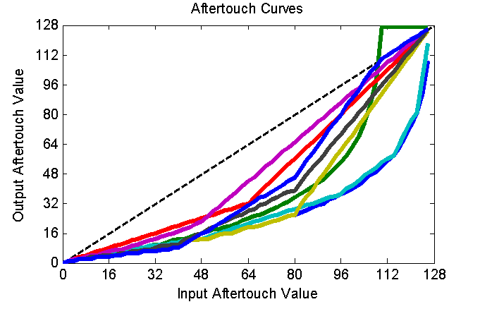
I then tried a whole bunch of other curves. Lots and lots. You can see many of them plotted together in the figure below. Some of them looked decent enough on paper to be worth trying on the Arduino. So, I coded them up as a simple look-up table and gave them a test drive.
After trying a bunch of curves, and after iterating the details of the most promising candidate, I finally converged to the curve below -- a curve made up of 4 linear segments. As you can see in the right-hand plot, the new onset and release seen in the green curve is very smooth. It gives me the best control (that I could find through this guess-try-and-tweak method) over both subtle and strong amounts of vibrato. It feels pretty darned good!
My remaining criticism with the response of my aftertouch is that it takes too much force to get the aftertouch started. Sadly, I have no control over when the aftertouch starts -- the start of the aftertouch is entirely set by when the keyscanning electronics decide to start generating MIDI aftertouch messages. Don't get me wrong, I think that the folks over at Keyparts UK set a very good general-purpose aftertouch threshold into their keyscanning electronics. I just think that *I* like my aftertouch to start with far less force than most other folks. I like it to start with a mere feather of a force...an amount that would drive other folks crazy.
To address this "problem", I'm thinking that there's probably a configuration setting in the keyscanning electronics that'll let me adjust the aftertouch threshold. The electronics are amazingly configurable and under continued development. I think that it's time for me to dive in and figure it out. Fun!